Railroad coupler mount

a coupler and rail technology, applied in washstands, scaffold accessories, lighting supports devices, etc., can solve the problems of affecting the operation of the coupler, affecting the service life of the coupler, so as to facilitate the installation and facilitate the removal or removal. , the effect of easy insertion

Active Publication Date: 2015-07-07
PROGRESS RAIL SERVICES
View PDF19 Cites 6 Cited by
  • Summary
  • Abstract
  • Description
  • Claims
  • Application Information

AI Technical Summary

Benefits of technology

[0010]It is therefore the object of the invention to mount to the coupler in a fashion that does not impede the mating of another coupler and avoids damage to the mount and equipment when mating another coupler.
[0011]Another object of the invention is to facilitate safety and ergonomics by being sufficiently compact to remain within or minimize protrusion from the width of mounted equipment and to be light weight.
[0012]Yet another object of the invention is to easily and quickly install to and remove from a coupler and to easily manufacture the device.

Problems solved by technology

However, when mating two couplers, mounts using or in close proximity to the coupler mating features prevent the couplers from mating or expose the mount and equipment to severe damage without first removing the mount and equipment from the coupler.
These coring holes and passages are only designed to facilitate the coupler casting process and lessen the coupler weight, but are otherwise unused in normal coupler operations.
Consequently, mounts that employ coring hole anchors large enough to span lengthwise coring hole pairs are inevitably heavy and often protrude beyond the equipment to be mounted, and this makes carrying the equipment more difficult.
Dismounted equipment is often carried at the user's side, and the propensity of the protruding mount to bump the user's leg or catch on clothing presents a safety hazard.
These additional mount components must be independently fabricated from the hook or finger and complicate manufacture of the mount.
This keeps the mount compact, but both jaws must pivot to fit variable coupler hole geometry, and the device requires multiple scissor arms with multiple pivots or a geared screw to actuate, which complicates manufacture of the mount.
This makes installation or removal of the mounts slow and tedious.

Method used


Image

  • Railroad coupler mount
  • Railroad coupler mount
  • Railroad coupler mount

Examples


Embodiment Construction

[0020]Reference will now be made in detail to preferred embodiments of the present invention, examples of which are illustrated in the accompanying drawings. Wherever possible, the same reference numbers will be used throughout the drawings to refer to the same or like parts.

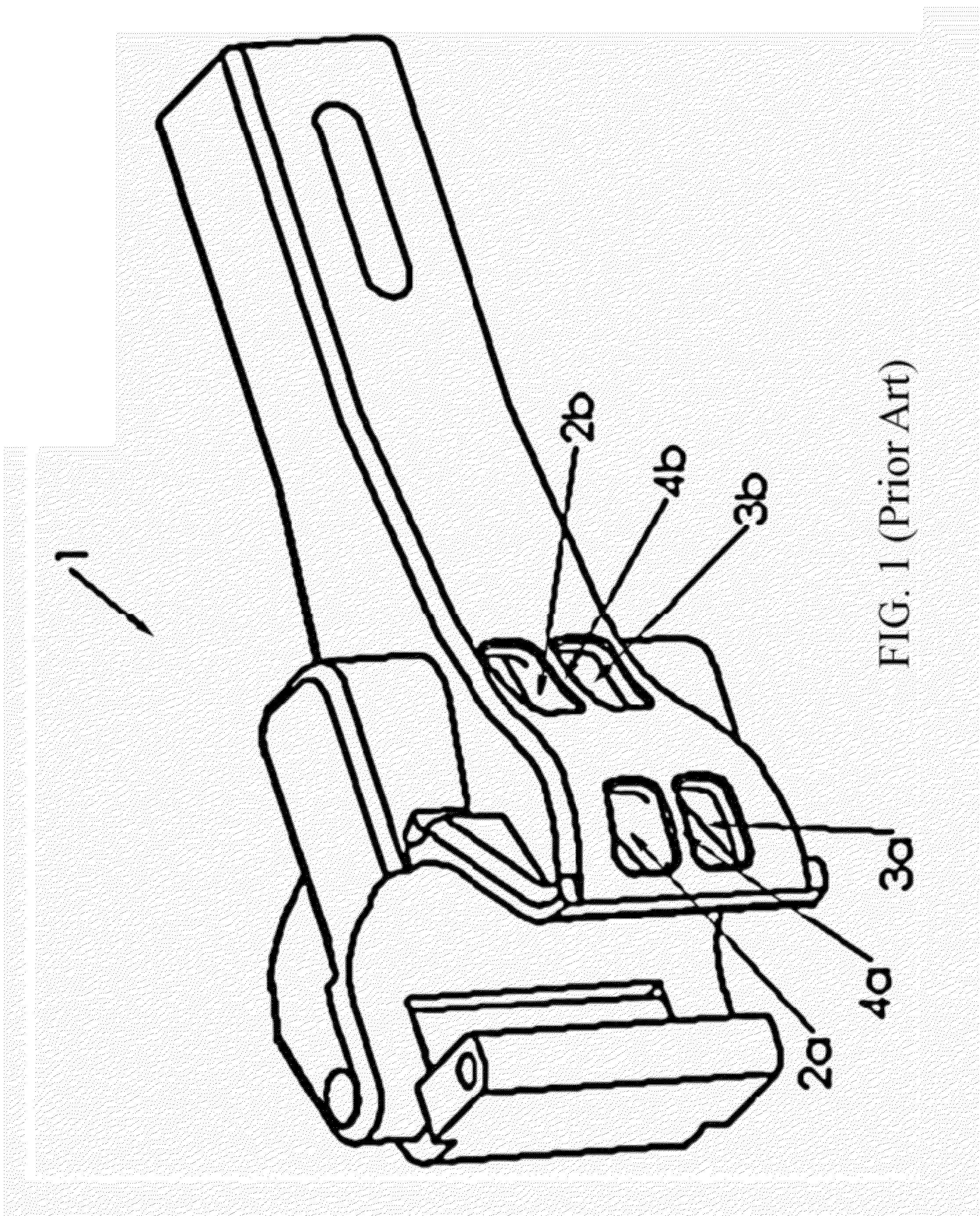
[0021]The present invention is an improved railroad coupler mount for attaching an end-of-train device (EOT), marker light, test gear, or other equipment to a conventional railroad coupler (e.g., as shown in FIG. 1), having at least one vertical pair of coring or relief holes and intermediate rib on the guard arm face such as 2a, 3a and 4a or 2b, 3b and 4b. The improved railroad coupler is low-profile and does not impede coupler-to-coupler juncture, nor is it in any way exposed to possible damage during coupler-to-coupler juncture. The improved railroad coupler improves safety and ergonomics.

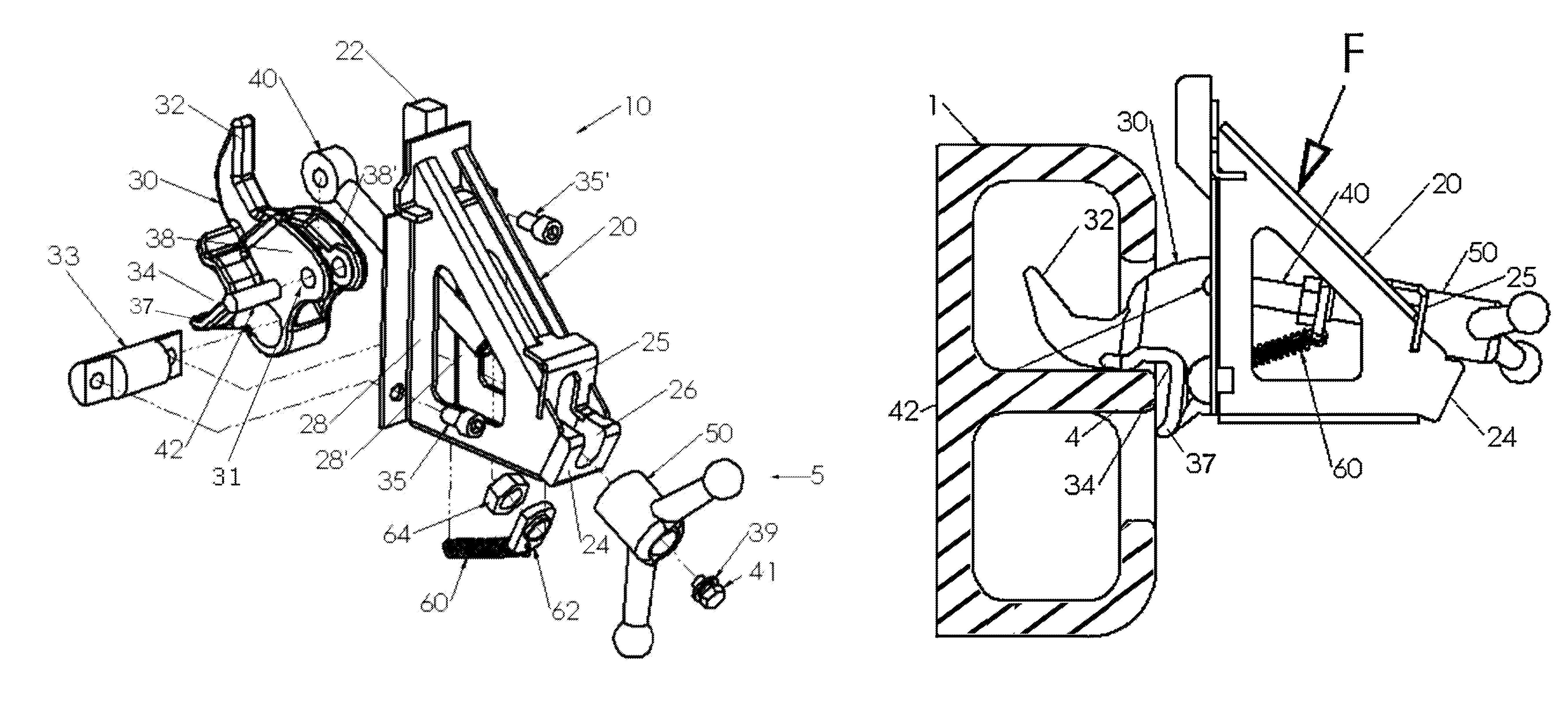
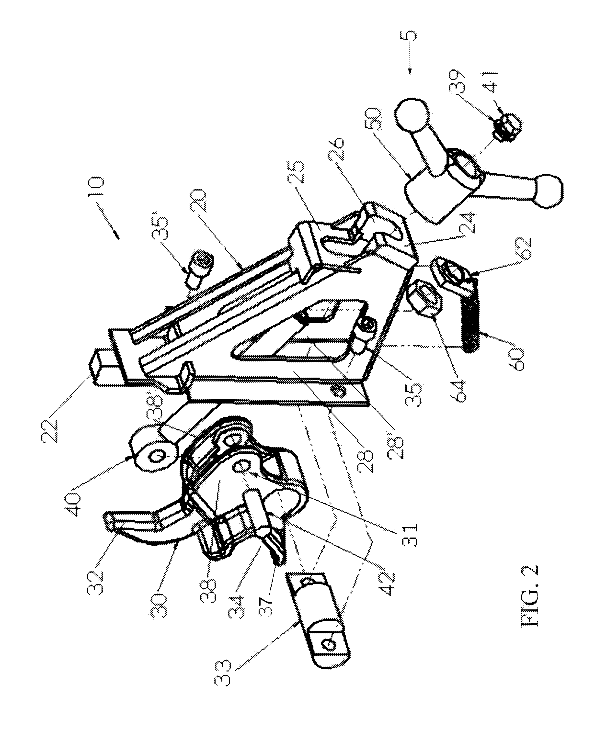
[0022]FIG. 2 is an exploded view of the coupler mount 10 according to a preferred embodiment. The components described her...


PUM


Abstract

An improved railroad coupler mount for attaching equipment, such as an end-of-train device (EOT), marker light, test gear, etc., to a railroad coupler. The mount is comprised of a pivoting lever with brace (a V- or U-shaped notch) that grips the rib between vertically spaced coupler coring holes and a lever tip that contacts the inner wall of the coupler top coring hole, a pad that bears against the exterior face of the coupler guard arm side and a mechanism that forcibly pivots the lever tip towards the pad on an axis roughly parallel to the coupler axis.

Description

CROSS-REFERENCE TO RELATED APPLICATION(S)[0001]The present application derives priority from U.S. provisional application Ser. No. 61 / 478,503 filed 23 Apr. 2011.BACKGROUND OF THE INVENTION[0002]1. Field of the Invention[0003]The present invention relates to improvements in railroad coupler mounts and, more particularly, railroad coupler mounts for attaching an end-of-train device (EOT), marker light, test gear, or other equipment to a railroad coupler.[0004]2. Description of the Background[0005]Railroad couplers are designed to connect rail cars together to form the train and generally have no provision to mount other devices or equipment. However, railroads often need to mount end-of-train telemetry devices (EOTs), marker lights, test equipment or other devices to the same railroad car coupler.[0006]Several railroad mounts for EOTs, marker lights and / or other apparatus have been devised using the coupler knuckle or other coupler features that are active when mating two couplers tog...

Claims


Application Information

Patent Timeline
Patent Type & Authority Patents(United States)
IPC IPC(8): B61L15/02B61L15/00B61G7/00B61G1/02B61G5/02B61G1/00B61G1/40B61G1/18B61G7/14B61G1/32
CPCB61L15/0054B61G7/00B61G1/02B61G5/02B61G1/40B61G1/32B61G1/18B61L15/02B61G7/14B61G1/00
Inventor EGERTON, GARY WILLIAM
Owner PROGRESS RAIL SERVICES
Why Eureka
Try Eureka