Supercharge Your Innovation With Domain-Expert AI Agents!

Subsidence control system

a control system and subsidence technology, applied in mining structures, transportation and packaging, chemistry apparatus and processes, etc., can solve the problems of resource recovery, resource volume, product quality, impact, etc., and achieve the effect of reducing the height and surface area of the crown and enclosing volum

Active Publication Date: 2015-07-14
RED LEAF RESOURCES
View PDF34 Cites 1 Cited by
  • Summary
  • Abstract
  • Description
  • Claims
  • Application Information

AI Technical Summary

Benefits of technology

The patent is about a new invention that has certain features and benefits. Sometimes, those features can be explained by simple details from the text, while other times, the benefits of the invention can be more complex and require more analysis. The technical effects of this invention have not been explicitly stated in this text, but it seems to have certain features and benefits that make it useful in a certain field. The patent should be read more carefully to determine the technical effects of this invention.

Problems solved by technology

However, these sources remain a difficult challenge in terms of economically competitive recovery.
Canadian tar sands have shown that such efforts can be fruitful, although many challenges still remain, including environmental impact, product quality, production costs and process time, among others.
Regardless, these reserves represent a tremendous volume and remain a substantially untapped resource.
Among typical oil shale processes, all face tradeoffs in economics and environmental concerns.
No current process alone satisfies economic, environmental and technical challenges.
While the cost savings resulting from avoiding mining can be achieved, the in-situ method requires heating a formation for a long period of time due to the extremely low thermal conductivity and high specific heat of solid oil shale.
Perhaps the most significant challenge for any in-situ process is the uncertainty and long-term potential of water contamination that can occur with underground freshwater aquifers.
It has been recognized by the present inventors that a potential drawback to this method and system lies in the subsidence of the hydrocarbon lean materials within the infrastructure over time causing the cap and any overburden to settle below the initial grade, potentially to the extent of creating a concave surface.
Settling below grade of the infrastructure may be undesirable from an environmental or reclamation point of view.
Further, materials surrounding the capsule often possess minimal or no tensile strength.
These materials may be placed in tension parallel to the capsule crown surface if the capsule surface settles below a horizontal plane to produce an increasingly concave surface and may subsequently separate or rupture as the cap of the infrastructure settles causing exposure of the contents within the infrastructure to the outside environment.
Exposure of lean shale or other earthen materials, which may contain minimal amounts of unremoved hydrocarbons, heavy metals and the like may be undesirable.

Method used


Image

  • Subsidence control system
  • Subsidence control system
  • Subsidence control system

Examples


Embodiment Construction

[0018]Reference will now be made to exemplary embodiments and specific language will be used herein to describe the same. It will nevertheless be understood that no limitation of the scope of the invention is thereby intended. Alterations and further modifications of the inventive features described herein, and additional applications of the principles of the invention as described herein, which would occur to one skilled in the relevant art and having possession of this disclosure, are to be considered within the scope of the invention. Further, before particular embodiments of the present invention are disclosed and described, it is to be understood that this invention is not limited to the particular process and materials disclosed herein as such may vary to some degree. It is also to be understood that the terminology used herein is used for the purpose of describing particular embodiments only and is not intended to be limiting, as the scope of the present invention will be def...


PUM


Abstract

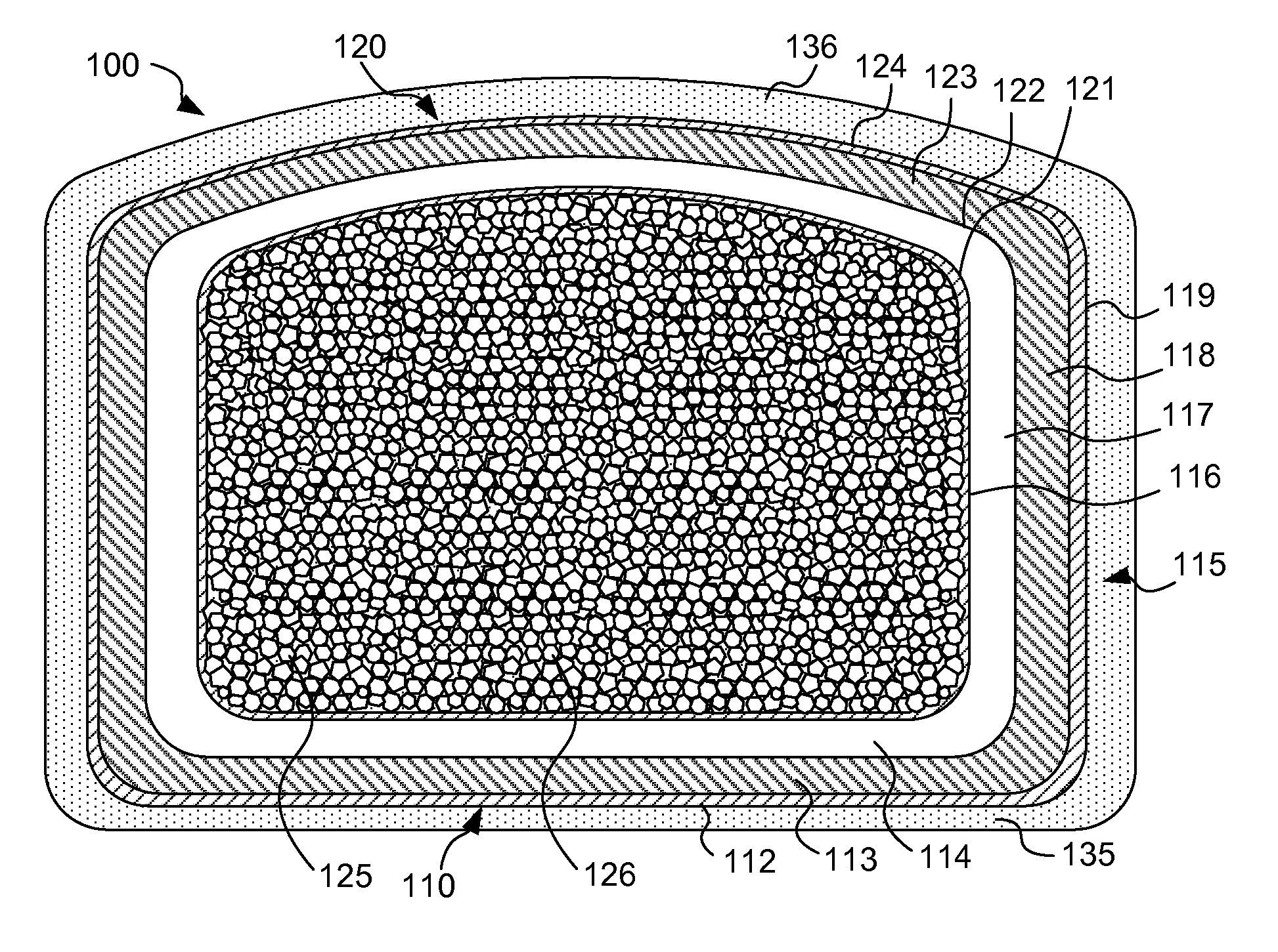
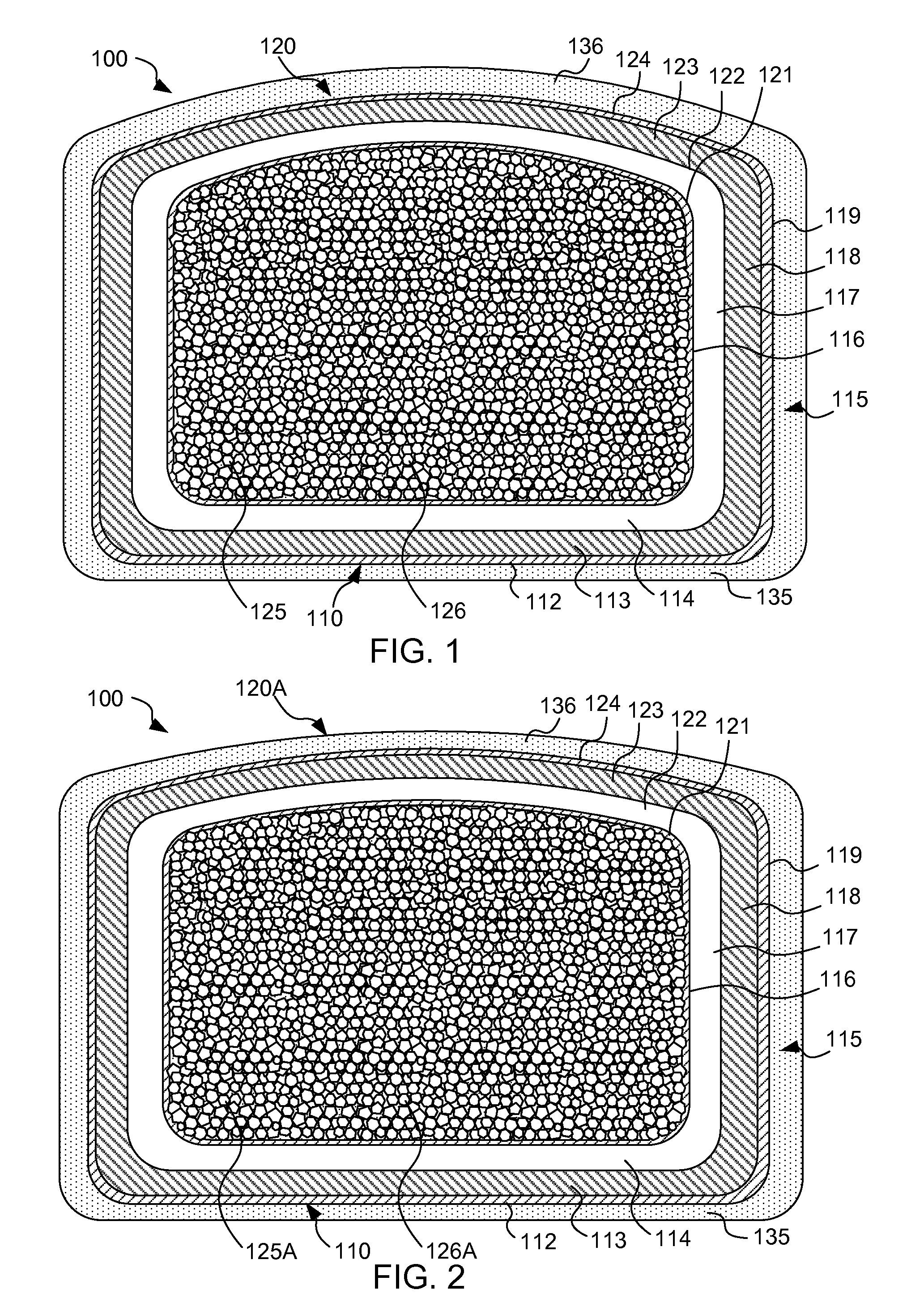
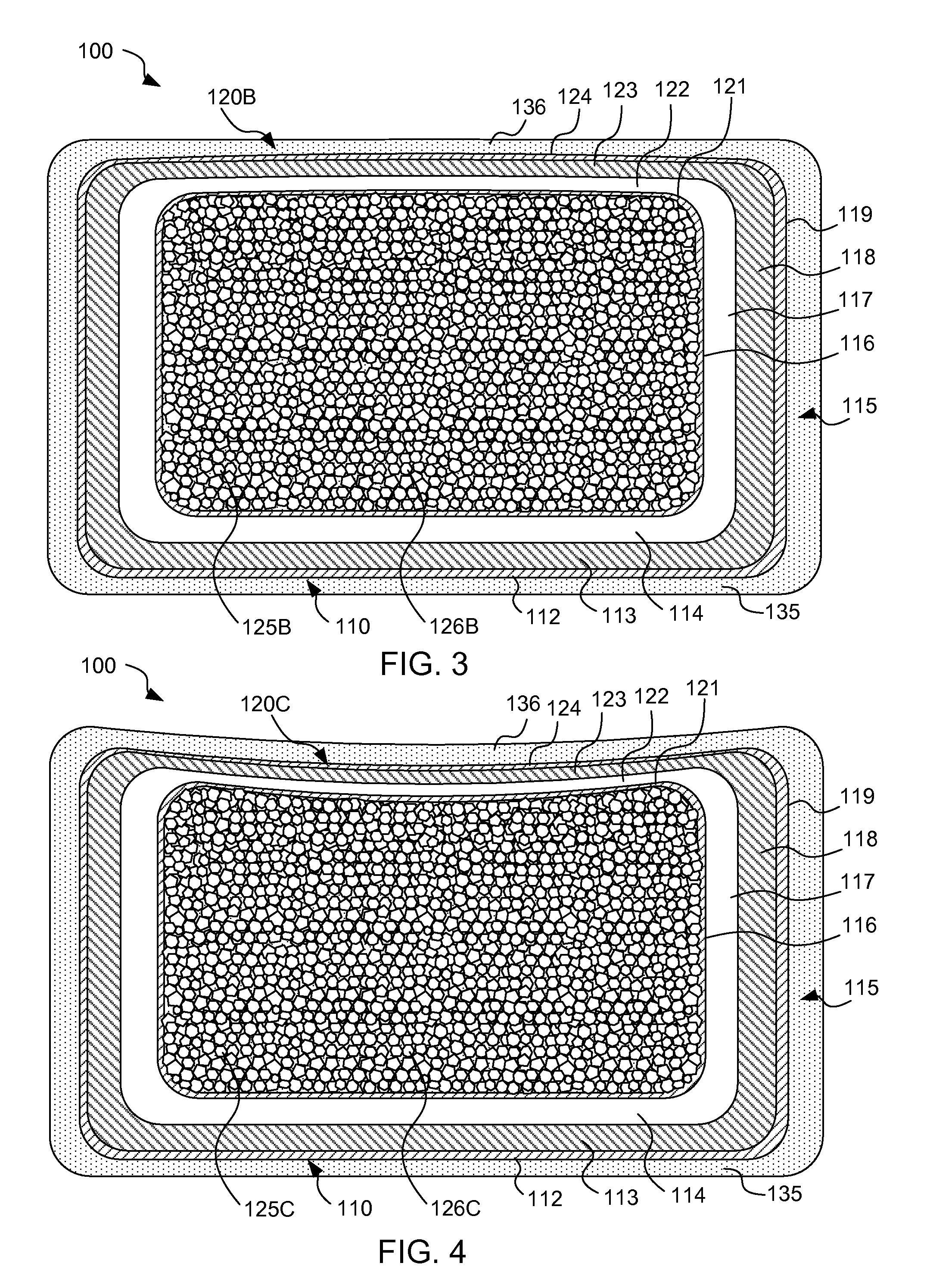
A method of maintaining structural integrity of a subsiding earthen fluid containment structure is disclosed and comprises forming a lined containment infrastructure (100) including a convex bulged crown portion (120), floor portion (110) and sidewall portions (115) which enclose a comminuted earthen material (126) within an enclosed volume (125) such that fluid flow from the lined containment compound is restricted. The bulged crown flattens, thickens and diminishes in surface area during subsidence of the comminuted earthen material as fluid is removed. The bulged crown is shaped to avoid tensile stresses which may otherwise result in breach or failure of lined containment during subsidence. Further, the lined containment structure can include an inner insulative layer and an outer impermeable seal layer having unique contributions as described in more detail herein.

Description

RELATED APPLICATION[0001]This application claims the benefit of U.S. Provisional Patent Application No. 61 / 263,261, filed Nov. 20, 2009, which is incorporated herein by reference.BACKGROUND OF THE INVENTION[0002]Global and domestic demand for fossil fuels continues to rise despite price increases and other economic and geopolitical concerns. As such demand continues to rise, research and investigation into finding additional economically viable sources of fossil fuels correspondingly increases. Historically, many have recognized the vast quantities of energy stored in oil shale, coal and tar sand deposits, for example. However, these sources remain a difficult challenge in terms of economically competitive recovery. Canadian tar sands have shown that such efforts can be fruitful, although many challenges still remain, including environmental impact, product quality, production costs and process time, among others.[0003]Estimates of world-wide oil shale reserves range from two to alm...

Claims


Application Information

Patent Timeline
Patent Type & Authority Patents(United States)
IPC IPC(8): B65G5/00E02D31/00
CPCB65G5/00E02D31/002B09B3/20B09C1/00C10B53/00E02D31/004
Inventor PATTEN, JAMES W.
Owner RED LEAF RESOURCES
Features
  • R&D
  • Intellectual Property
  • Life Sciences
  • Materials
  • Tech Scout
  • Unparalleled Data Quality
  • Higher Quality Content
  • 60% Fewer Hallucinations
Learn More