Damper unit

a technology of adampers and tyres, applied in the direction of interconnection systems, transportation and packaging, and suspensions that are resilient, can solve the problems of affecting affecting the stability of the vehicle, so as to improve the grip of the tyre, improve the control of the body movement, and improve the ride quality of the vehicl

Active Publication Date: 2015-07-14
MCLAREN AUTOMOTIVE
View PDF52 Cites 18 Cited by
  • Summary
  • Abstract
  • Description
  • Claims
  • Application Information

AI Technical Summary

Benefits of technology

[0003]A typical vehicle includes a suspension system between the wheels and body of the vehicle. The wheels are typically mounted on bearings and the bearings are attached to the body of the vehicle via a suspension linkage which supports the body of the vehicle on the bearings. The suspension linkage will usually include dampers that are used to control the travel of the suspension system and thus improve the ride quality of the vehicle, the grip of the tyres because of improved tyre contact with the ground, and the handling because of improved control of the motion of the body of the vehicle. The suspension linkage may also include components such as springs to also control the motion of the vehicle's body relative to the wheels. For example, the vehicle may have four wheels and be provided with a double wishbone suspension at each of the four wheels. The double wishbone suspension will be coupled between the bearing of the wheel and the body of the vehicle to allow the wheel to move relative to the body of the vehicle. A damper unit may be connected between one of the wishbones of the suspension and the body of the vehicle to control the movement of the wheel relative to the body of the vehicle.
[0006]In the above described system, the travel of the damper units is limited by the length of the shorter of the two chambers. Therefore, in effect, the two chambers have the same length of travel. This can also be seen by the two chambers sharing a common damper rod. If the two damper chambers are placed one on top of the other then the damper unit needs to be at least twice as long as the maximum travel of the complete damper unit. Such a length may be undesirable if such a length cannot be easily accommodated in the suspension system of a vehicle. For example, such a length may be undesirable in high performance cars where low vehicle height is important. The length of the damper unit can be reduced by reducing wheel travel and so the maximum travel of the damper unit or by using mechanical advantage to reduce damper travel. Alternatively, two separate damper units may be used side-by-side. However, in each case there are design compromises that are made, for example by having a much wider package size or reduced travel.
[0007]It would be desirable to have a damper unit for use in a system that provides independent stiffness and damping for both heave and roll that provides a desirable length of travel while being compact in package size.

Problems solved by technology

During the motion of the vehicle, the vehicle may be subject to heave, roll, pitch and warp.
Such a length may be undesirable if such a length cannot be easily accommodated in the suspension system of a vehicle.
For example, such a length may be undesirable in high performance cars where low vehicle height is important.
However, in each case there are design compromises that are made, for example by having a much wider package size or reduced travel.

Method used


Image

  • Damper unit
  • Damper unit
  • Damper unit

Examples


Embodiment Construction

[0025]The following description is presented to enable any person skilled in the art to make and use the system, and is provided in the context of a particular application. Various modifications to the disclosed embodiments will be readily apparent to those skilled in the art.

[0026]The general principles defined herein may be applied to other embodiments and applications without departing from the spirit and scope of the present invention. Thus, the present invention is not intended to be limited to the embodiments shown, but is to be accorded the widest scope consistent with the principles and features disclosed herein.

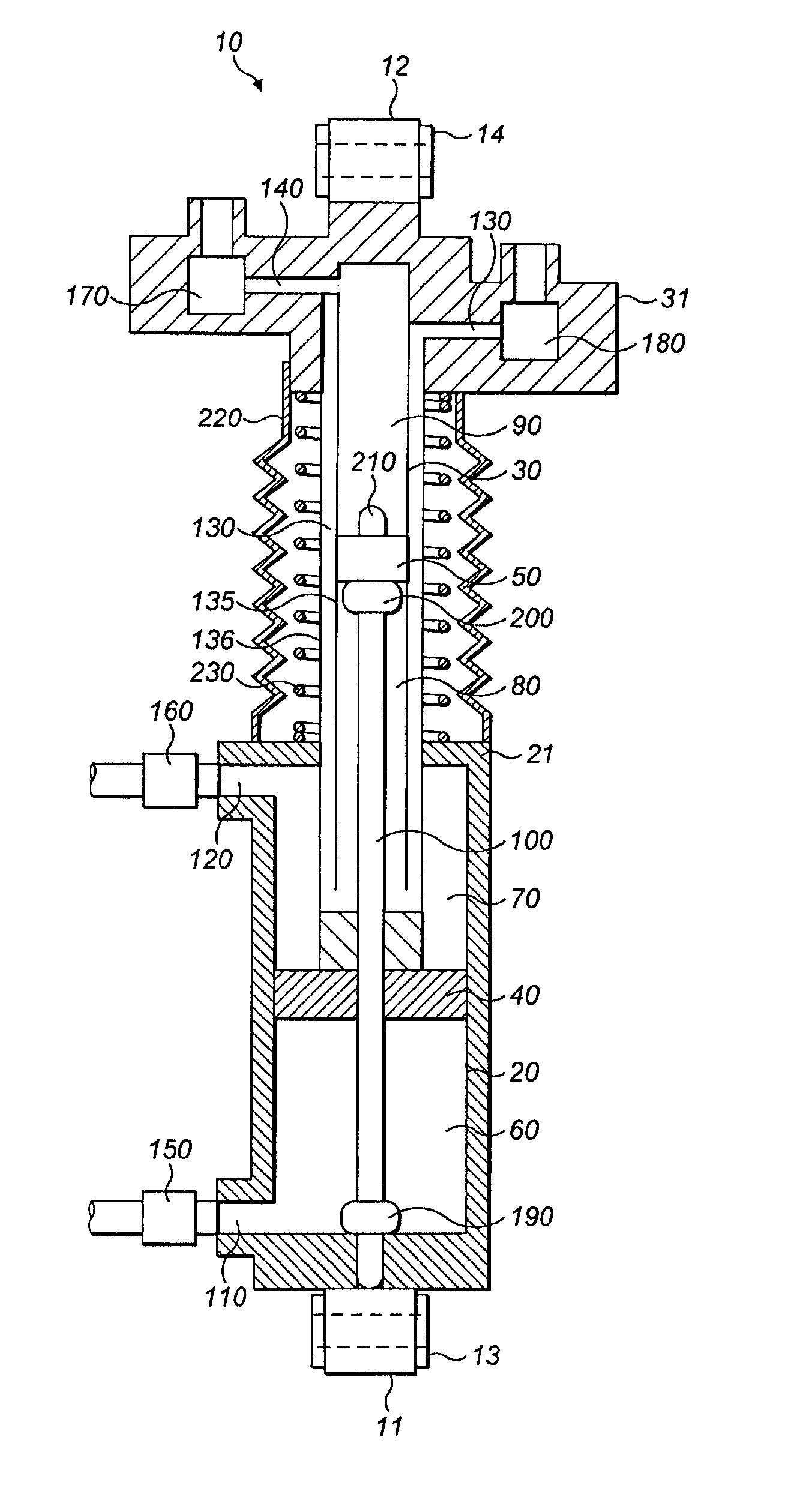
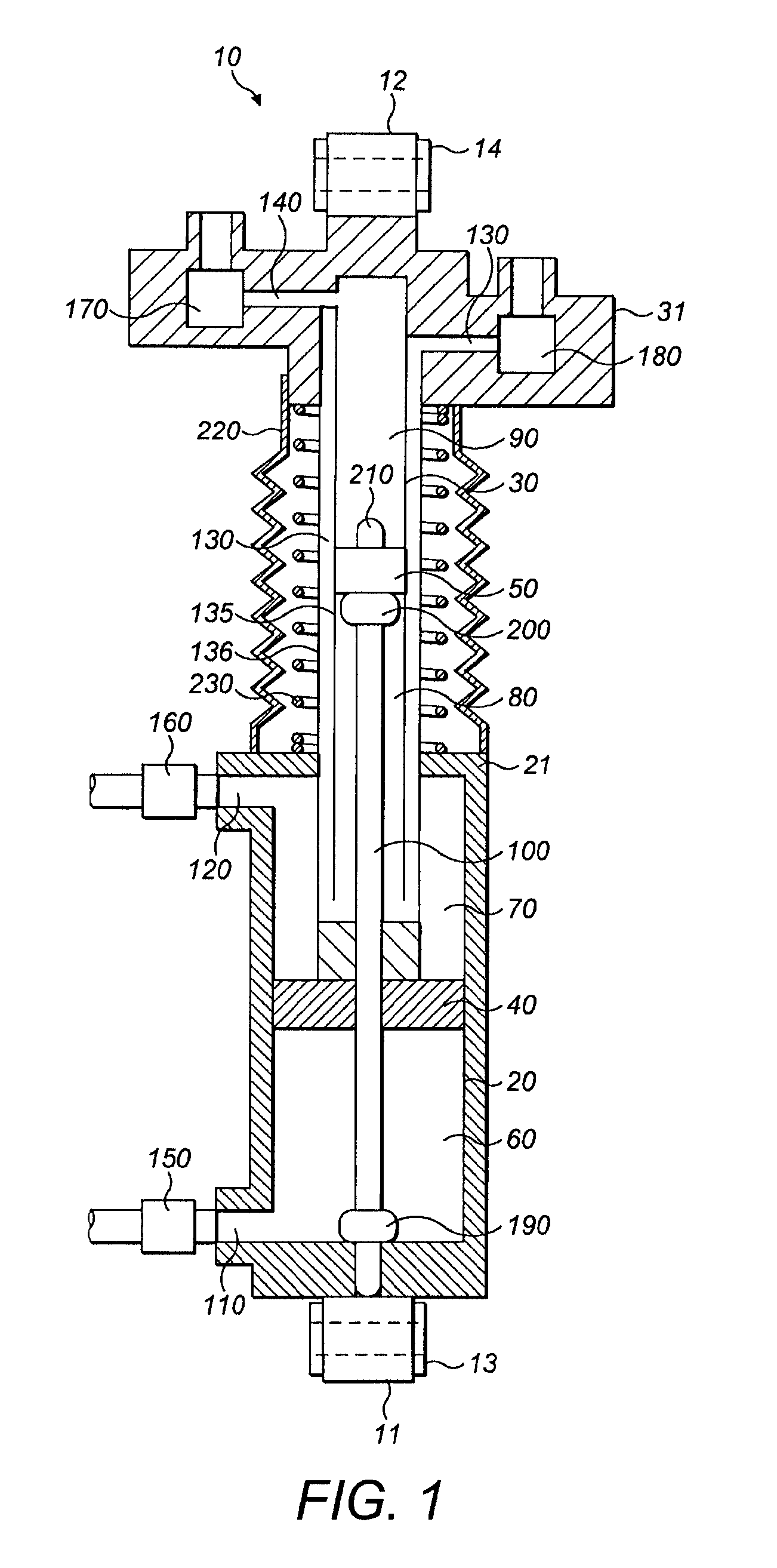
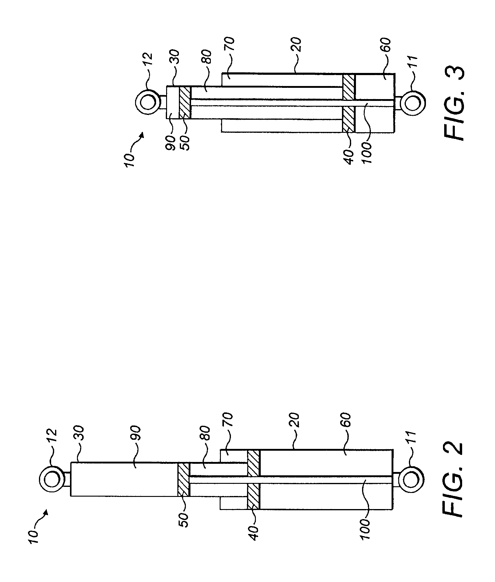
[0027]FIG. 1 shows a schematic diagram of a damper unit 10. The damper unit 10 has mounting points 11 and 12 by which the damper unit 10 may be attached to parts of a structure that can move relative to each other. For example, it may be attached between points on a suspension system for a vehicle. These mounting points 11 and 12 can move relative to each other by vi...


PUM


Abstract

A damper unit includes first and second chambers, a first piston dividing the first chamber into first and second volumes, and a second piston dividing the second chamber into third and fourth volumes. Each piston is moveable along the respective chamber. The second chamber has a cross-sectional area that is smaller than the cross-sectional area of the first chamber so that the second chamber at least partially slides inside the first chamber and at least part of the first chamber can be located around the outside of the second chamber. The first piston is attached to the part of the second chamber that slides inside the first chamber. The position of the second piston is fixed relative to the first chamber as the second chamber slides relative to first chamber. The length of the damper unit changes as the second chamber slides relative to the first chamber.

Description

CROSS-REFERENCE TO RELATED APPLICATIONS[0001]This patent application claims priority to Great Britain Patent Application GB 1303400.4, filed Feb. 26, 2013, entitled “Damper Unit,” which is incorporated by reference.BACKGROUND[0002]This invention relates to a damper unit suitable for use in a suspension system of a vehicle.BRIEF SUMMARY OF THE INVENTION[0003]A typical vehicle includes a suspension system between the wheels and body of the vehicle. The wheels are typically mounted on bearings and the bearings are attached to the body of the vehicle via a suspension linkage which supports the body of the vehicle on the bearings. The suspension linkage will usually include dampers that are used to control the travel of the suspension system and thus improve the ride quality of the vehicle, the grip of the tyres because of improved tyre contact with the ground, and the handling because of improved control of the motion of the body of the vehicle. The suspension linkage may also include c...

Claims


Application Information

Patent Timeline
Patent Type & Authority Patents(United States)
IPC IPC(8): F16F9/26B60G11/06F16F9/06B60G21/06B60G17/08
CPCF16F9/26B60G11/06B60G17/08B60G21/06F16F9/06B60G2300/27B60G11/56
Inventor HOULT, WILL
Owner MCLAREN AUTOMOTIVE
Why Eureka
Try Eureka