Check patentability & draft patents in minutes with Patsnap Eureka AI!

Charge pump regulator circuit with variable amplitude control

a pump regulator and variable amplitude technology, applied in process and machine control, instruments, apparatus without intermediate ac conversion, etc., can solve problems such as noise, ripple or jitter, and the inability to tolerate a certain amount of nois

Active Publication Date: 2015-07-14
QUALCOMM INC
View PDF41 Cites 2 Cited by
  • Summary
  • Abstract
  • Description
  • Claims
  • Application Information

AI Technical Summary

Benefits of technology

This design achieves a low noise output voltage and current, particularly at lower power levels, reducing interference in electronic devices like cell phones and improving radio link quality by minimizing noise coupled to the load circuit.

Problems solved by technology

A generally undesirable result of the use of such an oscillating signal is the presence of noise, i.e. ripple or jitter, in the output current and / or voltage of the charge pump regulator circuit, even after passing the output signal through an appropriate filter.
Most load circuits, though, can tolerate a certain amount of noise.

Method used


Image

  • Charge pump regulator circuit with variable amplitude control
  • Charge pump regulator circuit with variable amplitude control
  • Charge pump regulator circuit with variable amplitude control

Examples


Embodiment Construction

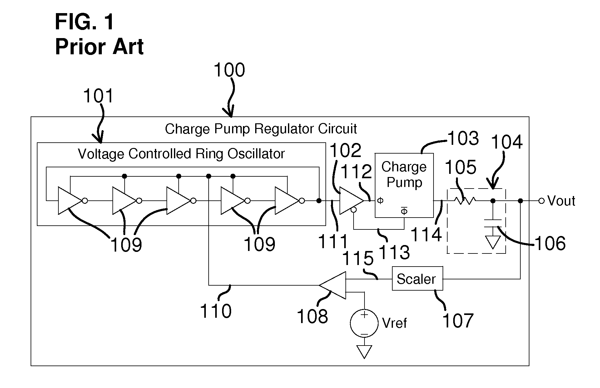
[0017]According to some embodiments, the present invention achieves an improved low noise output voltage (at least under some operating conditions) with a charge pump regulator circuit that has an oscillator and one or more charge pumps. The oscillator may be any appropriate type of device that can produce one or more oscillating signals depending on the needs of the particular embodiments. In some embodiments, the oscillator may be controlled by a variable voltage or variable current and may produce the one or more oscillating signals with a variable frequency, a variable voltage amplitude or a variable current amplitude, or appropriate combination thereof. In some of the embodiments, the oscillator may be a ring type oscillator that has a series of stages arranged in a ring, and the stages may be any appropriate type of stages, such as inverter stages, differential stages, etc. Additionally, the one or more charge pumps may be any appropriate type of device (or types of devices) t...


PUM


Abstract

A charge pump regulator circuit includes an oscillator and one or more charge pumps. One or more oscillating signals are generated by the oscillator. Each oscillating signal has a frequency or amplitude or both that are variable dependent on a variable drive signal. For some embodiments having multiple oscillating signals, each oscillating signal is phase shifted from a preceding oscillating signal. For some embodiments having multiple charge pumps, each charge pump is connected to receive a corresponding one of the oscillating signals. Each charge pump outputs a voltage and current. For some embodiments having multiple charge pumps, the output of each charge pump is phase shifted from the outputs of other charge pumps. A combination of the currents thus produced is provided at about a voltage level to a load.

Description

CROSS-REFERENCE TO RELATED APPLICATIONS[0001]This patent document is a continuation-in-part of patent application Ser. No. 13 / 544,815 filed Jul. 9, 2012, which is incorporated herein by reference in its entirety.BACKGROUND OF THE INVENTION[0002]Charge pump regulator circuits may be used to generate an output voltage and current to power a load circuit in an electronic device. There are different types of charge pump regulator circuits, each having different strengths and weaknesses. A common feature of such charge pump regulator circuits is an oscillating signal that is used to generate the output voltage and current. A generally undesirable result of the use of such an oscillating signal is the presence of noise, i.e. ripple or jitter, in the output current and / or voltage of the charge pump regulator circuit, even after passing the output signal through an appropriate filter. Most load circuits, though, can tolerate a certain amount of noise. Nevertheless, various trends in the dev...

Claims


Application Information

Patent Timeline
Patent Type & Authority Patents(United States)
IPC IPC(8): G05F1/10H02M3/07
CPCG05F1/10H02M3/07
Inventor MOLIN, STUART B.LOU, PERRYKEMERLING, CLINT
Owner QUALCOMM INC
Features
  • R&D
  • Intellectual Property
  • Life Sciences
  • Materials
  • Tech Scout
  • Unparalleled Data Quality
  • Higher Quality Content
  • 60% Fewer Hallucinations
Learn More