
Speed limiter

a technology of speed limiter and map data, applied in the direction of electric control, vehicle sub-unit features, instruments, etc., can solve the problems of difficult operation of the vehicle, inability to realistically update the map data at short intervals, and difficulty in operating the vehicle, and achieve the effect of high versatility

Active Publication Date: 2015-07-21
SUBARU CORP
View PDF44 Cites 2 Cited by
  • Summary
  • Abstract
  • Description
  • Claims
  • Application Information

AI Technical Summary

Benefits of technology

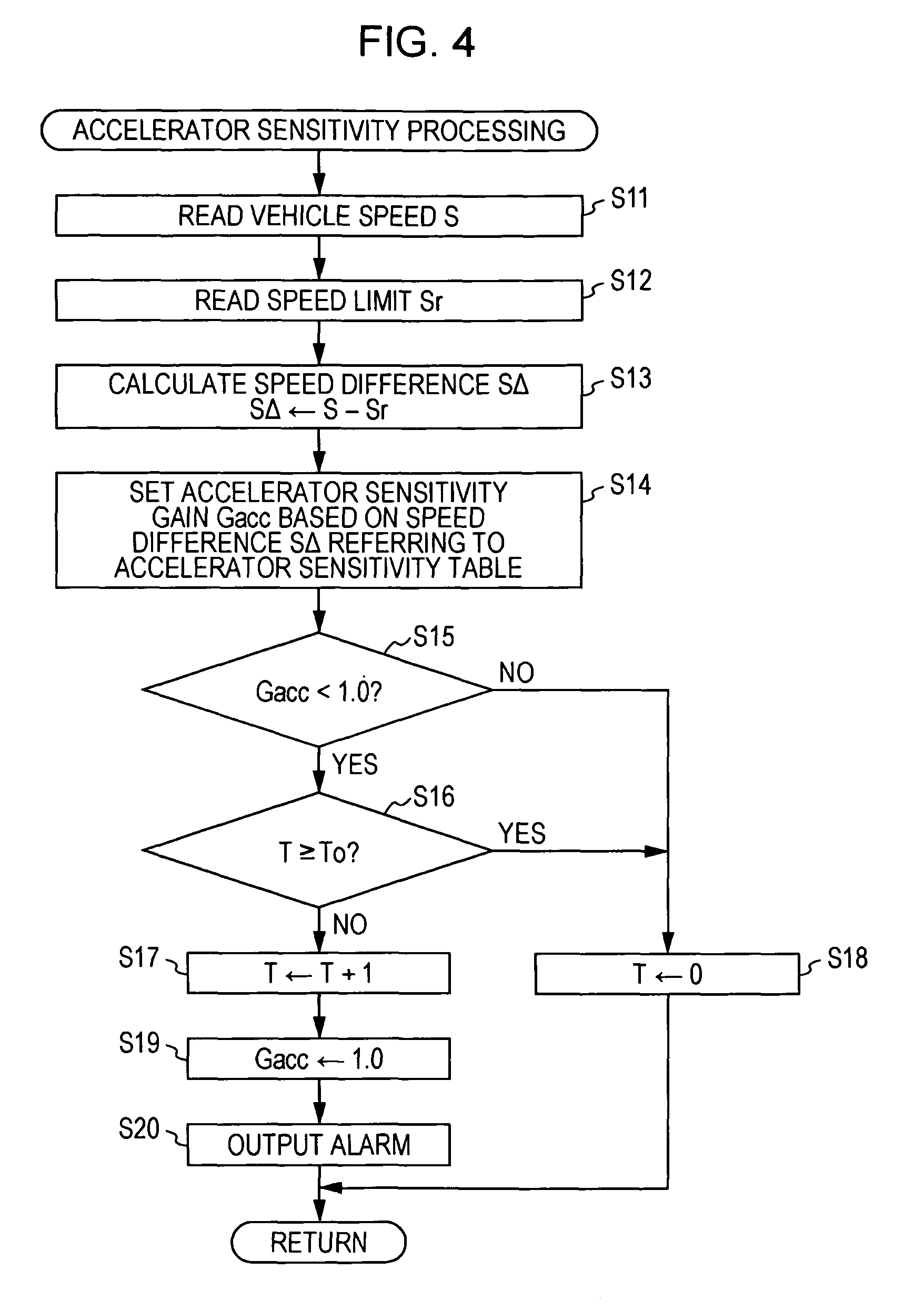
The present invention provides a speed limiter that can recognize a speed limit of a road without requiring a navigation system. The speed limiter can encourage the driver to drive within the speed limit without compellingly regulating the speed of the vehicle. This results in improved safety and efficiency of the vehicle and reduced discomfort for the driver. The speed limit can be detected through capturing images of a speed sign. Additionally, the speed limiter can limit the acceleration and correct the throttle valve opening degree based on the speed excess, ensuring that the driver stays within the speed limit.

Problems solved by technology

However, it is difficult to operate the vehicle while constantly recognizing the vehicle speed of the traveling road.
It frequently occurs that the driver drives at a normal legal speed, missing a road sign or misunderstanding that a speed limit is not set for the traveling road.
Although it is possible to accommodate these cases by updated the map data, the update of the map data at short intervals requires a significant cost, and thus is not realistic.
However, when the vehicle is traveling in a region where a beacon cannot be received, accurate speed limit information cannot be obtained.
In this case, if, for example, vehicles are traveling with a short inter-vehicle distance on a crowded road and only the speed of the subject vehicle is limited, following vehicles are prevented from running smoothly, and moreover, the subject vehicle may cause congestion.

Method used


Image

  • Speed limiter
  • Speed limiter
  • Speed limiter

Examples


Embodiment Construction

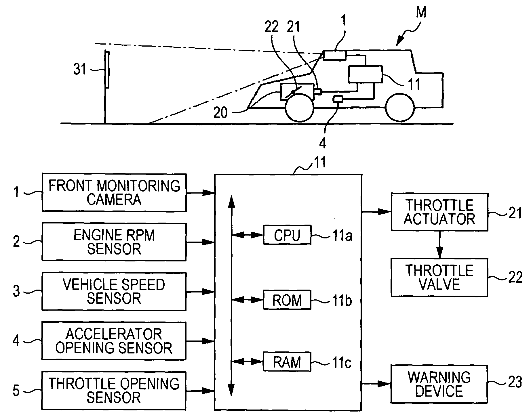
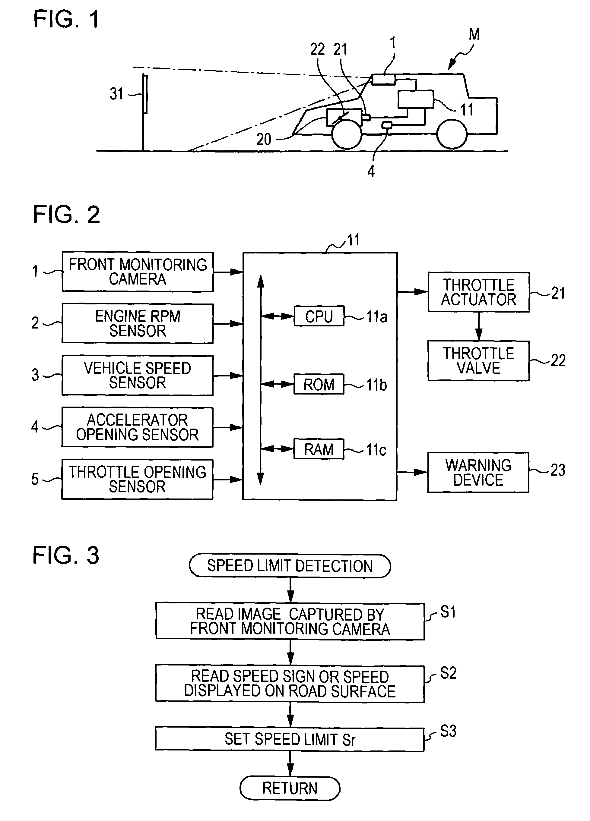
[0025]An embodiment of the present invention will hereunder be described with reference to the drawings. As shown in FIG. 1, a subject vehicle M, which is an automobile or the like, includes: a front monitoring camera 1 as a capturer that captures a front of the subject vehicle M; a throttle opening control unit 11 that identifies a speed sign 31 and the like from an image captured by the front monitoring camera 1 and recognizes a speed limit displayed thereon to set a throttle opening degree with respect to an accelerator opening degree according to a relationship between the speed limit and a vehicle speed of the subject vehicle M; and a throttle actuator 21 that is provided to an engine 20 and operates according to a control signal from the throttle opening control unit 11. The throttle actuator 21 adjusts an opening degree of a throttle valve 22.

[0026]As shown in FIG. 2, the throttle opening control unit 11 mainly includes a microcomputer having a CPU 11a, a ROM 1b, a RAM 11c an...


PUM


Abstract

Provided is a speed limiter, wherein a vehicle speed is detected, and a speed limit displayed on a speed sign is detected based on an image captured by a front monitoring camera. A speed difference between the vehicle speed and the speed limit is calculated, and an accelerator sensitivity gain is set using the speed difference as a parameter. Then an accelerator opening degree is corrected with the accelerator sensitivity gain to obtain a pseudo accelerator opening degree. A target throttle opening degree is set based on the pseudo accelerator opening degree and an engine rpm.

Description

BACKGROUND OF THE INVENTION[0001]1. Field of the Invention[0002]The present invention relates to a speed limiter that recognizes a speed limit for a road on which a subject vehicle is traveling, based on an image captured by a front monitoring camera, and changes characteristics of throttle opening with respect to accelerator opening when a difference between the speed of the vehicle and the speed limit exceeds a predetermined value.[0003]2. Description of the Related Art[0004]A driver generally recognizes a speed limit displayed on a road sign or a road-surface sign on a road to determine whether or not the speed of a subject vehicle is within the speed limit. When the vehicle speed exceeds the speed limit, the driver controls the vehicle speed by performing a decelerating operation such as a reduction in a pressing amount of the accelerator pedal so as to make the vehicle speed fall within the speed limit.[0005]However, it is difficult to operate the vehicle while constantly recog...

Claims


Application Information

Patent Timeline
Patent Type & Authority Patents(United States)
IPC IPC(8): B60K31/00B60K31/18F02D41/02F02D11/10B60K31/04B60K31/02
CPCB60K31/18F02D11/105F02D41/0205B60K31/00B60K31/02B60K31/042B60K31/185B60K2031/0091B60K2310/244B60W2510/0638B60W2540/10B60W2550/22B60W2710/0605B60Y2400/3015F02D2200/501F02N2300/306B60W2555/60
Inventor KII, YUJIMARUYAMA, TASUKUMATSUURA, MUNENORI
Owner SUBARU CORP
Learn More