Spring-loaded retention and release mechanism for use on clipless bicycle pedals

a technology of a release mechanism and a clipless bicycle, which is applied in the direction of vehicle cranks, mechanical devices, vehicle components, etc., can solve the problems of no means for cyclists to be supported, difficulty in removing the toe clip from the pedal, and ungainly activity, etc., to achieve easy removal, less effort, and easy release of the shoe adapter

Inactive Publication Date: 2015-07-28
SWIFT PAUL
View PDF6 Cites 4 Cited by
  • Summary
  • Abstract
  • Description
  • Claims
  • Application Information

AI Technical Summary

Benefits of technology

[0015]Insertion of the cleat adapter into a clipless pedal having the present invention retention and release mechanism is the same as with the prior art, in that the shoe cleat or toe clip is inserted into the front receptor and snapped into the rear receptor, with the present invention in place of the standard rear receptor. Removal of the shoe cleat or toe clip does not follow the prior art. There is no need for any sharp twisting movement of the ankle, instead, merely pressing on the spar lifts the rear receptor at the opposite end of the spar upward, thereby releasing the shoe adapter or toe clip. There need not be a lot of upward movement, only enough movement to sufficiently release the adapter. Pressing on the spar is usually done by hand and by the cyclist. In other words, the cyclist, having a shoe still attached to the pedal, can just reach down and press on the spar to release a shoe adapter. Additionally, anyone can press on the spar to help the cyclist. For the removal of toe clips, the same process is available, or the cyclist's foot can be removed first and then push on the spar to release the toe clip. The mechanical advantage provided by the spar means that very little upper body strength is required from the person attempting to release the shoe adapter or toe clip, particularly as compared to the prior art. Children and the elderly will experience no difficulty in releasing a shoe adapter or toe clip like they have in the prior art. Everyone using this device, those both with and without upper body strength, will be able to remove shoe adapters and toe clips with ease and grace. The preferred embodiment of the spar has grips along the spar to aid the user. If a cyclist has been sweating, or has hands that are moist from sweat from gloves and the like, the cyclist's hands won't slide off the spar, and instead, the cyclist will have a non-slip, frictional location on which to press down on the spar. This, too, is absent in the prior art, and is yet another advantage of the present invention.
[0016]The retention and release mechanism of the present invention is preferably a spring-loaded device. The default position of the present invention is in the retention mode. It is when force is exerted on the spar that the present invention enters the release mode.
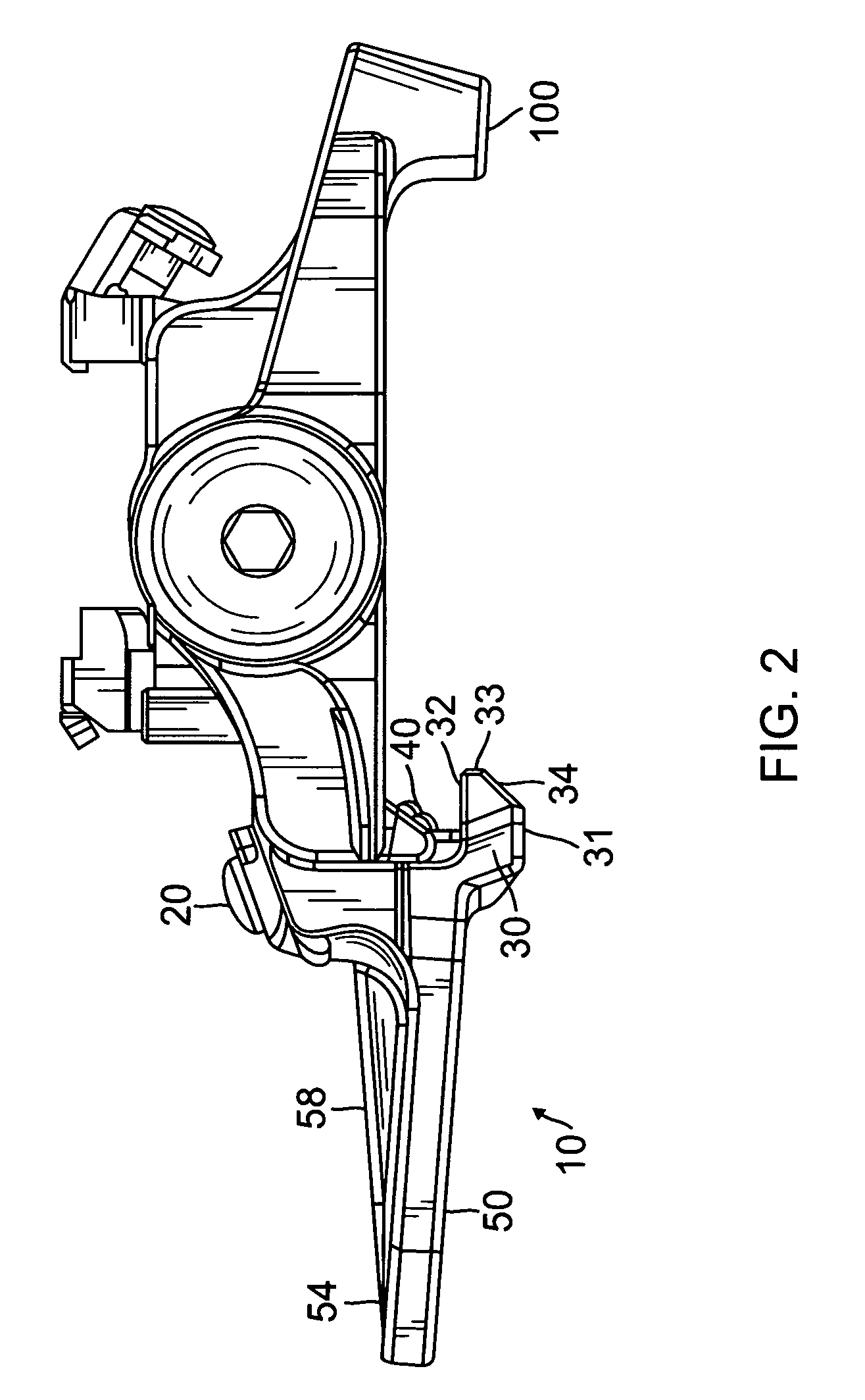
[0017]The lateral spar is of a length sufficient to provide the least amount of effort on the part of the user and yet not interfere with the cyclist or with the pedal movement. The spar should not hit the ground at the end of the down-cycle or at the beginning of the up-cycle of the peddling process. The spar preferably has a grip to further aid and ease the release of the shoe adapter. The spar may have braces, preferably underneath the spar, to support and buttress the spar. The spar may be made of any material that is appropriate for rear adapter receptors.
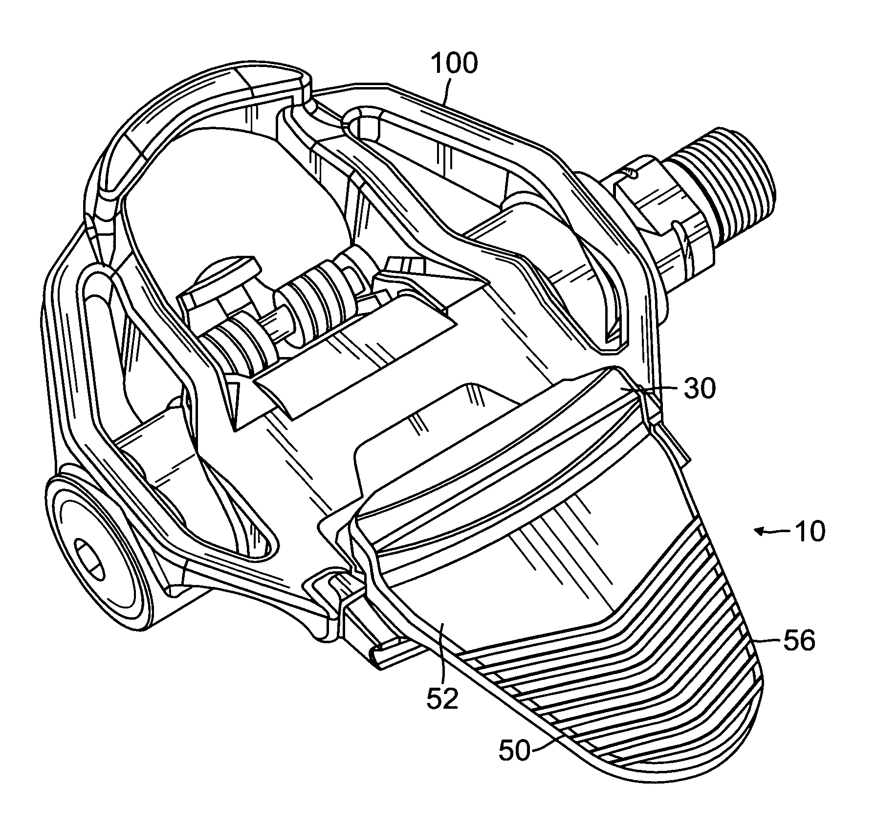
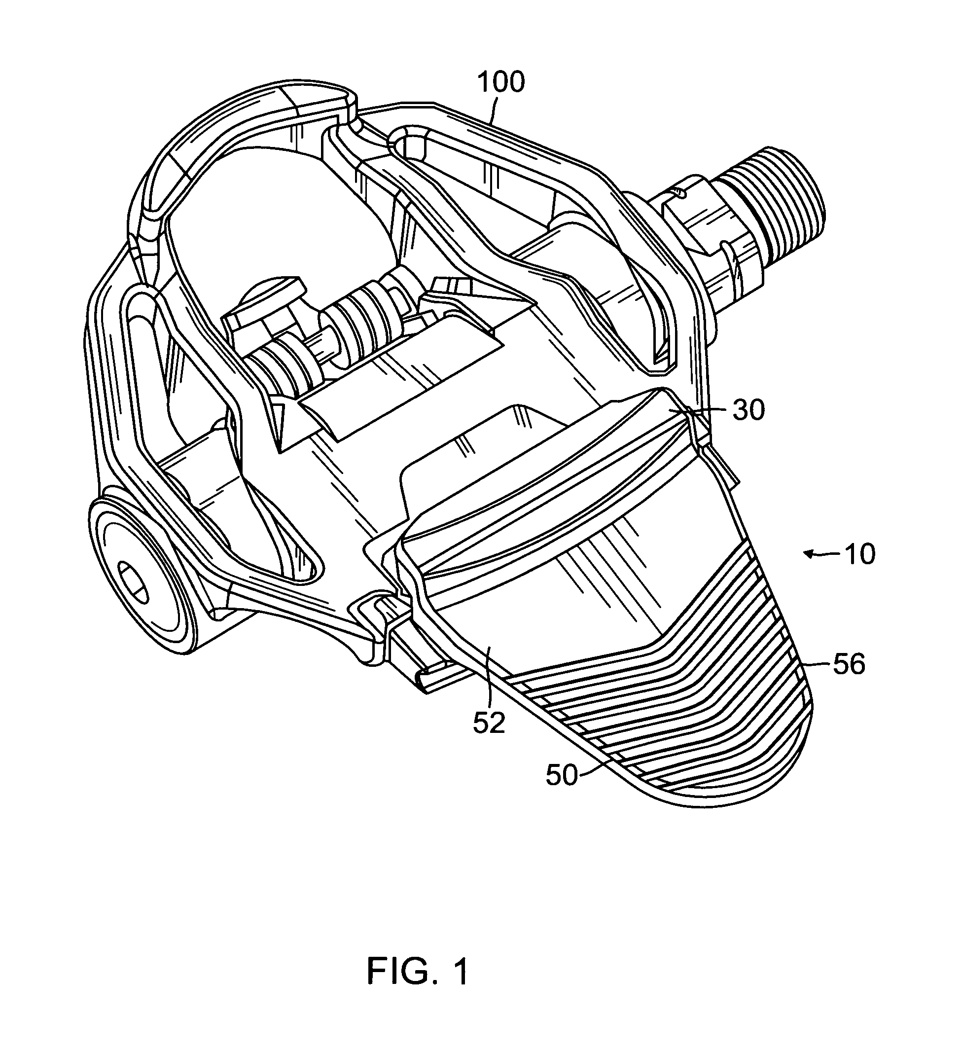
[0018]The present invention operates by first being inserted in a clipless pedal, a double-sided clipless pedal and the like, as the rear retainer in the clipless pedal. A toe clip or shoe adapter, having already been inserted into the clipless pedal, is removed quickly and easily in the following manner. Downward pressure is exerted, usually by hand, on the back end of the pedal on the spar of the present invention rear retainer. The presence and length of the spar allows the user to easily overcome the resisting force of the tension spring actuator, using just a little downward pressure, thereby stretching the tension spring or springs, resulting in the cleat retainer lifting its clamp head off the back of the toe clip or shoe adapter. Prior to the exertion of a downward pressure on the spar, the tension spring(s) actuator had provided a force on the clamp head so that the clamp head could keep pressure on the rear retainer of a toe clip or shoe adapter to hold it securely in place. Downward pressure on the spar results in overcoming the resisting force of the spring(s) actuator and raising of the clamp head. Raising of the clamp head means that the toe clip or shoe adapter is available to be removed from the pedal. All of these actions occur simultaneously with the exertion of downward pressure on the spar, which means that as soon as someone pushes down on the spar, the toe clip or shoe adapter is removed. Additionally, the presence, length and location of the spar provide a further advantage to the clipless pedal overall, because it means that the present invention rear retainer and release mechanism requires far less force to release a toe clip or shoe adapter than that required by the prior art, because the present invention rear retainer and release mechanism not only provides an actual place for the hand to grab a hold of and press down on, but also has grips, both of which are unique in the industry, and because the present invention rear retainer and release mechanism creates a faster, easier, and elegant solution to the afore mentioned problems in the prior art.
[0019]It is an object of the present invention to provide a spring-loaded bicycle cleat retaining and releasing mechanism to provide a mechanical advantage in order to reduce the amount of force needed to cause the cleat retaining mechanism to move away from the retained bicycle cleat.
[0020]It is an additional object of the present invention to provide a cleat retaining and releasing mechanism that provides a cleat removal that does not require a sharp motion that is lateral and in or parallel to the plane of the pedal face.

Problems solved by technology

This causes problems because removing the cleat from the pedal in this manner requires strength, in that the cyclist's ankles must be strong enough to make the sharp twist strong enough to escape the hook and strong enough not to be damaged by the twisting.
Since both feet of the cyclist are affixed to the pedals, there is no means for the cyclist to be supported if at least one foot is not released from the pedal when the bike comes to a stop.
However, the problem then remains as to how to remove the toe clip from the pedal.
This can be a strenuous and ungainly activity.
Bruised knuckles, broken nails, and scraped wrists are not uncommon results when trying to remove these toe clips, and even so, removal is not guaranteed and multiple attempts are generally required.
This can be embarrassing for cycling and indoor-cycling students who just can't get their pedal cleats off of their pedals, and also embarrassing for cycling instructors and indoor-cycling class instructors who will appear incompetent and uncoordinated in front of their classes when trying to assist students in the removal of toe clips.
Additionally, this method of removal requires quite a bit of upper body strength.
Another significant limitation of these tools is that they are limited only for the use of removing toe clips, and not for the cleated shoe.
There is lacking in the prior art a device that can aid in the removal of both a toe clip and cleated shoe.
There is no known prior art that addresses all these limitations.

Method used


Image

  • Spring-loaded retention and release mechanism for use on clipless bicycle pedals
  • Spring-loaded retention and release mechanism for use on clipless bicycle pedals
  • Spring-loaded retention and release mechanism for use on clipless bicycle pedals

Examples


Embodiment Construction

[0047]Although specific embodiments of the present invention will now be described with reference to the drawings, it should be understood that such embodiments are by way of example only and merely illustrative of but a small number of the many possible specific embodiments which can represent applications of the principles of the present invention. Various changes and modifications obvious to one skilled in the art to which the present invention pertains are deemed to be within the spirit, scope and contemplation of the present invention as further defined in the appended claims.

[0048]There is shown in FIG. 1 the retention and release mechanism 10 of the present invention in its operative relationship with a double-sided clipless pedal 100. The figures presented herein illustrate a single retention and release mechanism on only one side of a double-sided clipless pedal. It should be noted that the present invention can work with a single-sided clipless pedal and can also be presen...


PUM


Abstract

A retention and release mechanism for use on clipless bicycle pedals employed to achieve a mechanical advantage in the retention and release of shoe clip adapters and toe clips and other adapters. A preferred embodiment of the mechanism fits within existing clipless pedals, thus replacing existing rear retainers, and comprises a means by which it is affixed to the clipless pedal, a cleat retaining formation, a spring actuator and a specialized rearward extending spar. The cleat retaining formation has a special surface which facilitates entering a clip adapter or toe clip into retention mode. Release mode is effectuated by pressure on the spar which then engages the spring actuator to open the cleat retaining formation. The mechanism may be used on any type of clipless pedal and with any type of cleat adapter.

Description

BACKGROUND OF THE INVENTION[0001]1. Field of the Invention[0002]This invention relates to bicycle pedals and in particular, to rear retention mechanisms that accommodate a variety of bicycle shoe cleats and street shoe adapters. Use of the invention provides a mechanical advantage to cyclists and allows cyclists using bicycle shoe cleats or street shoe adapters in conjunction with clipless bicycle pedal systems to quickly, and with very little energy, release the cleat or adapter from the bicycle pedal, in a manner not seen before in the prior art.[0003]2. Description of the Prior Art[0004]The ubiquitous use of bicycles for pleasure, business and sport has resulted in a blossoming of new technologies related to this industry. One of the areas of interest is improving the pedal of bicycles and the way the foot and the pedal interact for maximum power transfer and for comfort. The current preference in modern bicycle pedal design is an arrangement that locks the pedal onto either spec...

Claims


Application Information

Patent Timeline
Patent Type & Authority Patents(United States)
IPC IPC(8): B62M3/00B62M3/08B62M3/16
CPCB62M3/086B62M3/16Y10T74/217
Inventor SWIFT, PAUL
Owner SWIFT PAUL
Why Eureka
Try Eureka