Wind power generator

a wind power generator and generator technology, applied in the direction of propellers, propulsive elements, water-acting propulsive elements, etc., can solve the problems of specialized personnel's operation difficulties and relatively long setup time of wind power generators, and achieve the effect of simple and cheap implementation

Inactive Publication Date: 2015-07-28
BONFIGLIOLI RIDUTTORI
View PDF7 Cites 2 Cited by
  • Summary
  • Abstract
  • Description
  • Claims
  • Application Information

AI Technical Summary

Benefits of technology

[0008]The purpose of the present invention is to provide a wind power generator which is free from the drawbacks described above and which is of simple and cheap implementation.

Problems solved by technology

The wind power generators of known type described above have the serious drawback that the correct coupling of the output gear of each gearmotor with the relative crown gear involves the removal of all the fastening bolts, the rotation of the gearmotor around its own longitudinal axis in such a way to exploit the eccentricity between the longitudinal axis of the gearmotor and the rotation axis of the output gear, the new fixing of the fastening bolts, and, therefore, serious operational difficulties on the part of specialized personnel and relatively long setup time of the wind power generator.

Method used


Image

  • Wind power generator
  • Wind power generator
  • Wind power generator

Examples


Embodiment Construction

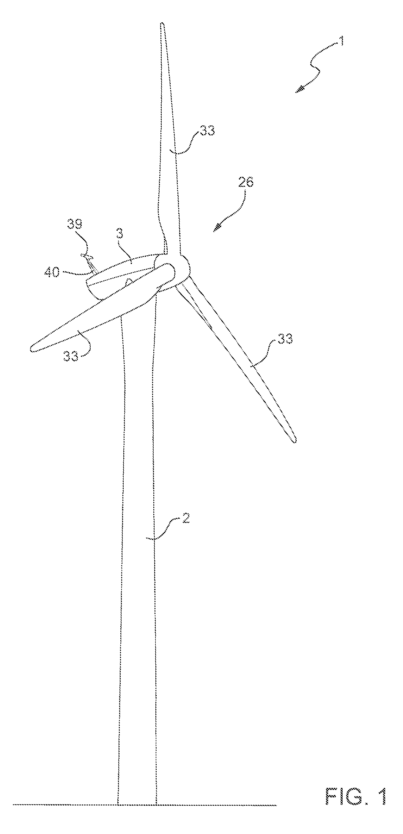
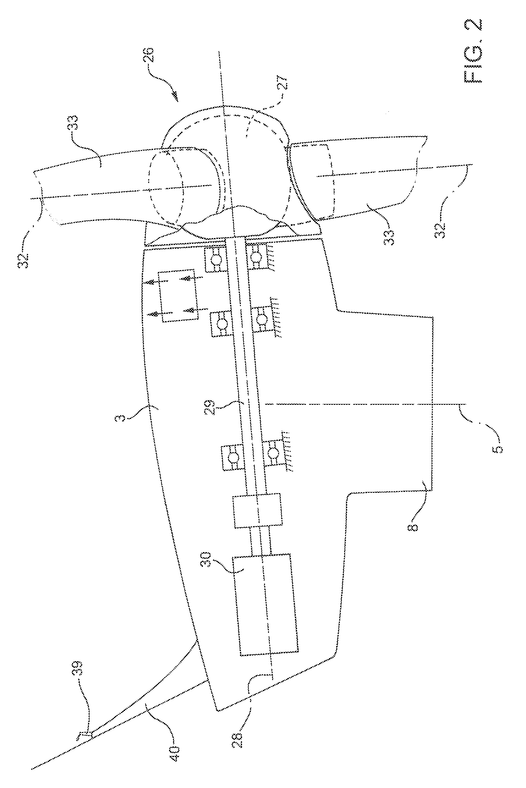
[0016]With reference to FIGS. 1 and 2, number 1 indicates as a whole, a wind power generator comprising a support tower 2, which is anchored to the ground, and supports a nacelle 3 coupled in a rotatory manner to an upper end of the tower 2 to oscillate with respect to the tower 2 and under the thrust of an orienting device 4, around a given rotation axis 5.

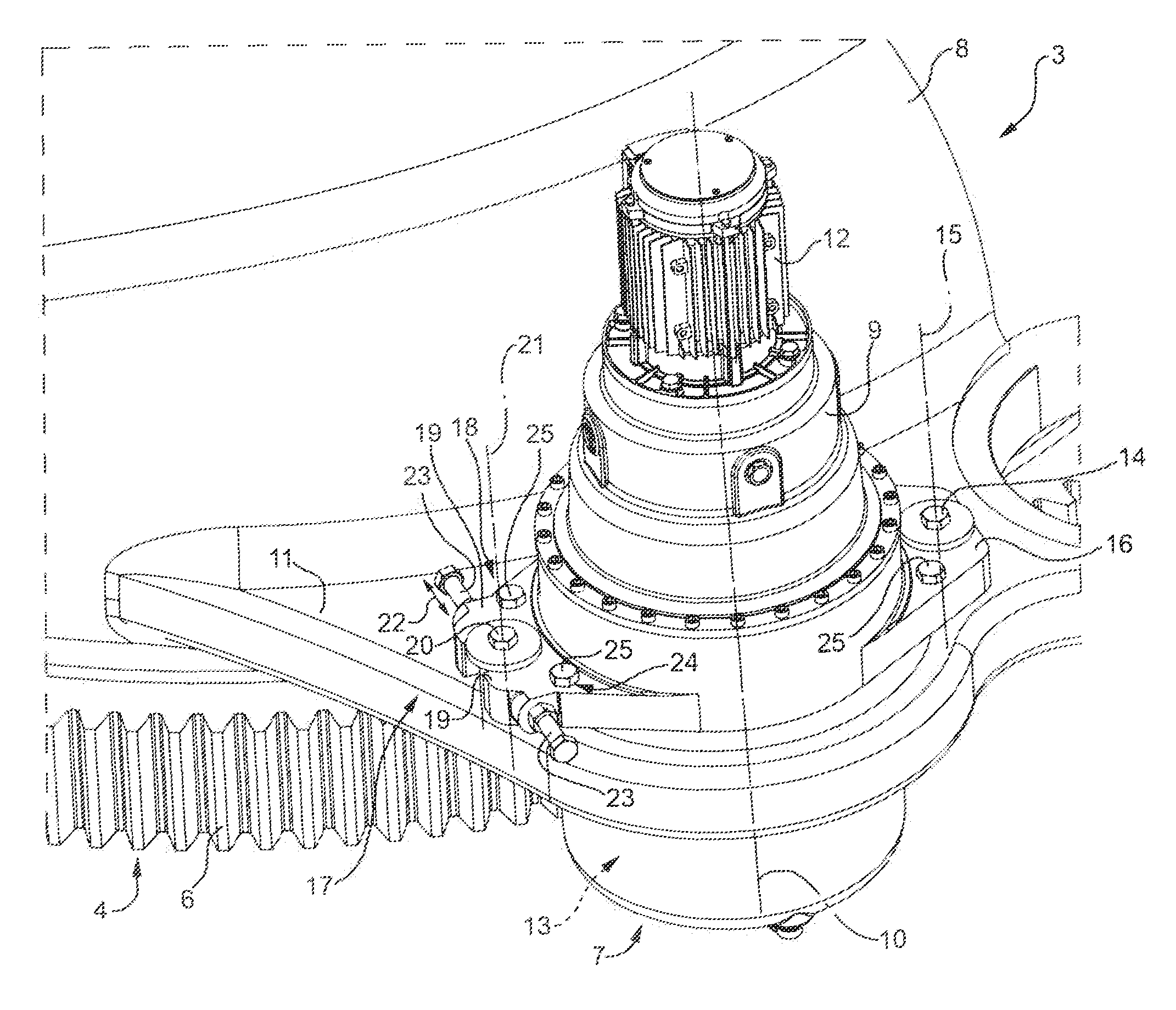
[0017]As shown in FIGS. 3 and 4, the device 4 comprises, in this case, a crown gear 6 fixed to the upper end of the tower 2 coaxially with axis 5, and a plurality of gearmotors 7, which are distributed around the axis 5, and are fixed to a sleeve 8 (FIG. 2) protruding downwardly from the nacelle 3 coaxially to the axis 5 itself.

[0018]Each gearmotor 7 comprises a substantially cylindrical containing casing 9, which has a longitudinal axis 10 substantially parallel to the axis 5, extends through a support bracket 11 or protruding radially outwardly from the sleeve 8 above the crown gear 6, and carries connected at a top end an elec...


PUM


Abstract

A wind power generator having a nacelle, which is mounted to an upper end of a support tower, supports in rotary manner a rotor, and is oriented around a rotation axis by an orienting device provided with at least one gearmotor. The gearmotor presents an output gear coupled with a crown gear fixed to the support tower and is hinged to the nacelle so as to rotate around a fulcrum axis, which is substantially parallel to the rotation axis under the thrust of an actuation device.

Description

[0001]The present invention relates to a wind power generator.[0002]In particular, the present invention relates to a wind power generator of the type comprising a support tower; a nacelle coupled in a rotary manner to an upper end of the support tower so as to rotate around a first rotation axis; and a rotor comprising, in turn, a central hub coupled in a rotatory manner to the nacelle and a plurality of blades coupled in a rotatory manner to the same central hub so as to rotate around respective second rotation axes.[0003]The position of the nacelle around the first rotation axis is selectively controlled by a first orienting device comprising a first crown gear mounted on the upper end of the support tower coaxially to the first rotation axis, and a plurality of first gearmotors, which are fixed to the nacelle, are distributed around the and first rotation axis, each presenting a respective first output gear coupled with the first crown gear.[0004]The position of each blade aroun...

Claims


Application Information

Patent Timeline
Patent Type & Authority Patents(United States)
IPC IPC(8): F03D7/02F03D1/06
CPCF03D7/0224F03D1/0658F03D7/0204F05B2260/4031F05B2260/74F05B2260/76F05B2260/79Y02E10/721Y02E10/723Y02E10/72
Inventor TORCELLI, ANDREAZINZANI, GIOVANNICASAMENTI, GUSTAVO
Owner BONFIGLIOLI RIDUTTORI
Why Eureka
Try Eureka