Shielding integrity testing for cable drop

a shielding integrity and cable drop technology, applied in the field of subscriber installations, can solve the problems of no control or even knowledge of other devices by the bcs operator, noise sources may be present, and the same is not true for subscriber installations, so as to achieve the effect of easy operation and little additional expense or weigh

Inactive Publication Date: 2015-07-28
COMSONICS
View PDF14 Cites 0 Cited by
  • Summary
  • Abstract
  • Description
  • Claims
  • Application Information

AI Technical Summary

Benefits of technology

[0007]It is therefore an object of the present invention to provide an arrangement for measuring RF signal ingress and shielding effectiveness that can be incorporated at little additional expense or weight into current test equipment or provided as a lightweight and easily operated accessory for such test equipment that can quantitatively measure shielding effectiveness in a subscriber installation.

Problems solved by technology

While expenditures for good design of the signal distribution portion of a BCS are economically effective, the same is not true for subscriber installations.
Nevertheless, the BCS operator has no control over or even knowledge of other devices that may be present at a subscriber site that may be sources of potentially large electromagnetic signals within the bands of frequencies at which the BCS operates.
Many potential sources of such noise such as electric motors in heating / cooling systems, refrigerators, dishwashers, fans and the like or even electric lighting and entertainment devices that are seldom thought of as radio frequency (RF) noise sources may be present and radiate substantial RF noise.
Further, inadequate assembly by the subscriber of well-designed components that may be as simple as inadequate tightening of a connector or the use of readily available and inexpensive but low quality components may function as a shielding flaw allowing ambient RF noise or broadcast signal ingress into the BCS.
Moreover such noise can accumulate for a plurality of subscriber installations along the BCS system and be summed by the BCS system itself until it may reach a level which compromises upstream signaling.
Unfortunately, arrangements for quantitatively measuring signal ingress at a subscriber site have only been capable of measuring noise levels above the intended signal levels on the BCS or have required additional expensive and cumbersome equipment for indirectly measuring effectiveness of shielding.

Method used


Image

  • Shielding integrity testing for cable drop
  • Shielding integrity testing for cable drop
  • Shielding integrity testing for cable drop

Examples


Embodiment Construction

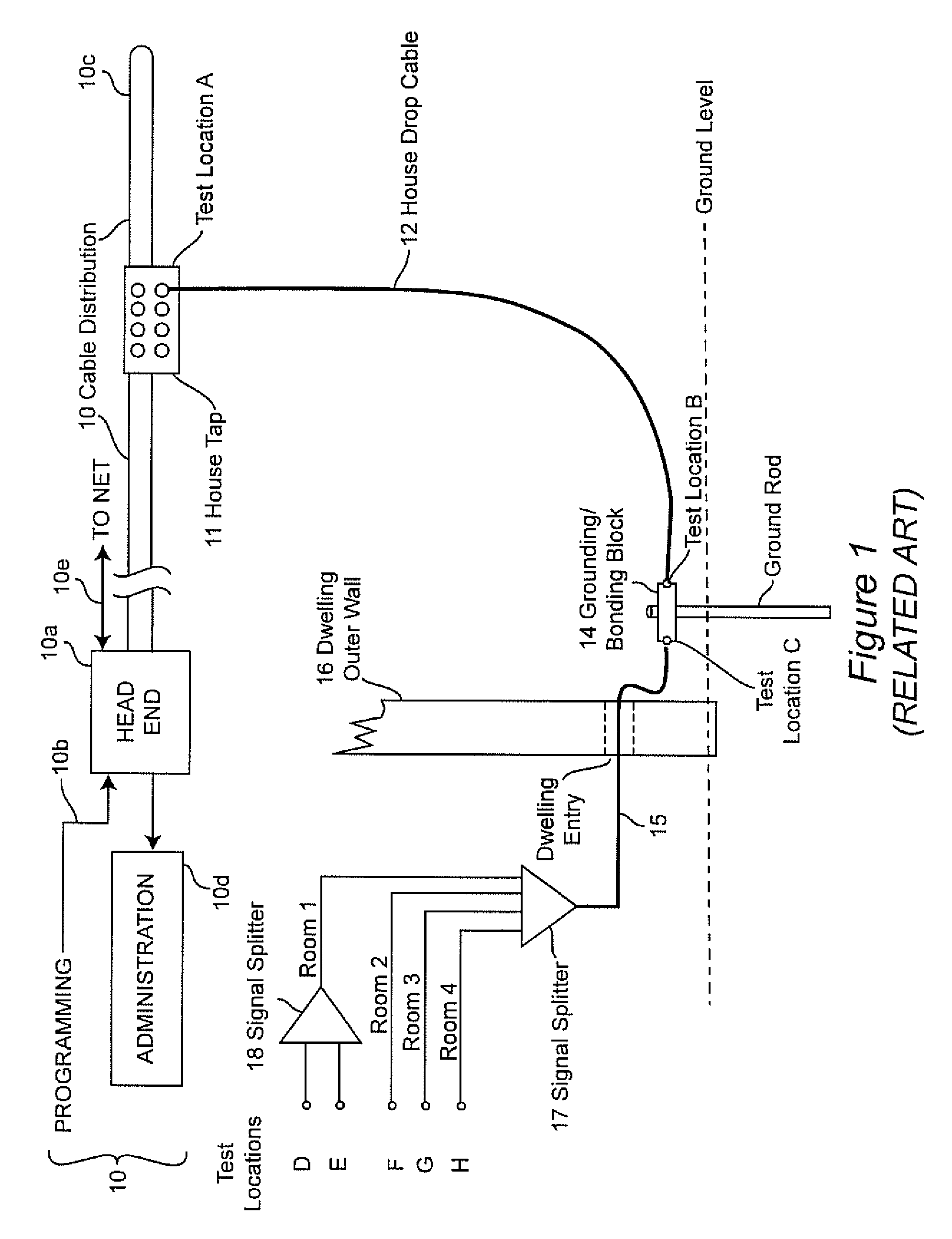
[0015]Prior to discussing the invention in detail, prior known techniques for measuring signal ingress or resistance to signal ingress at a subscriber installation will be briefly summarized. It is believed that such a summary will facilitate an understanding of the invention and provide an appreciation for the meritorious effects produced thereby.

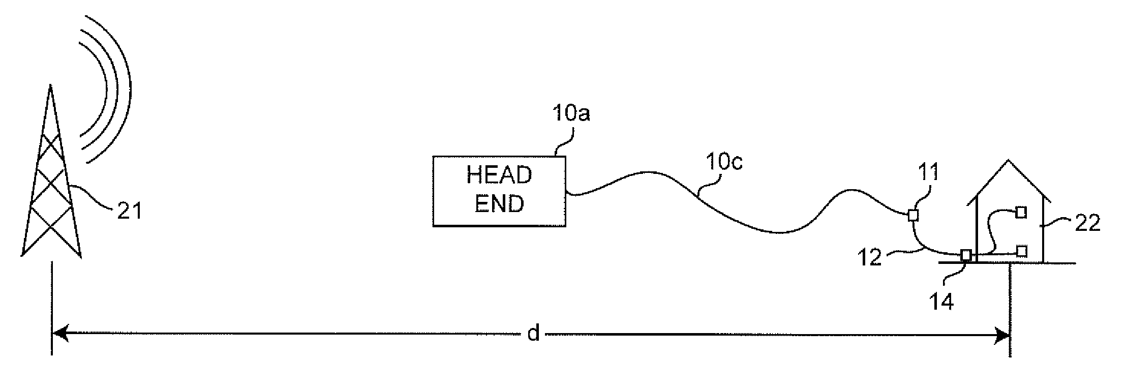
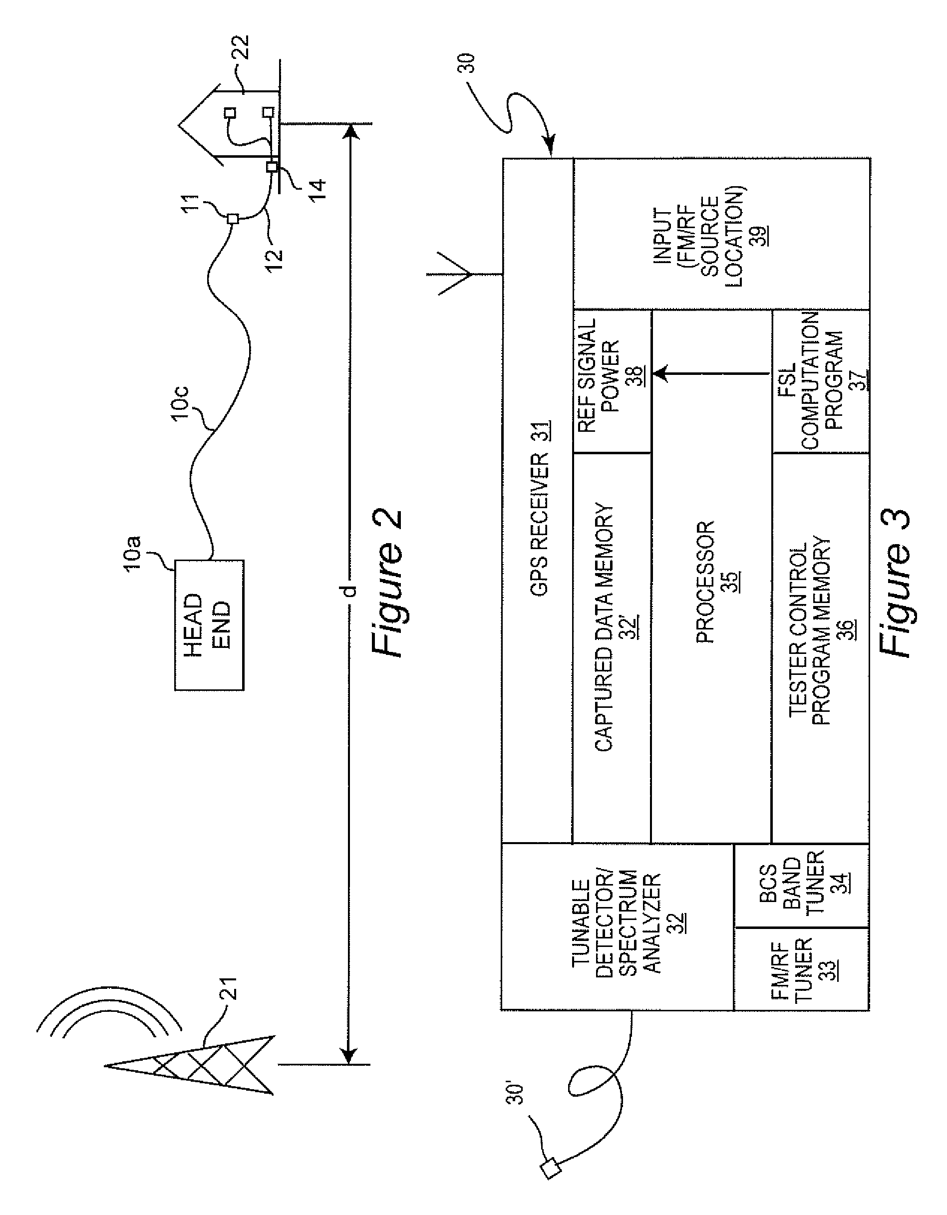
[0016]U.S. Pat. No. 5,777,662 to Zimmerman, assigned to the assignee of the present invention and hereby fully incorporated by reference, is directed to a system for testing shielding integrity and measuring resistance to signal ingress at a subscriber installation. For this purpose, a portable transmitter is provided to radiate an identifiable signal, preferably including global positioning system (GPS) coordinates of the transmitter, at a known (low) power level in the vicinity of the subscriber installation (or any other location within the geographic extent of the BCS) and to seek to detect a power level of that signal on the BCS syste...


PUM


Abstract

Signal ingress at an installations site forming a part of a broadband communication system is quantitatively evaluated for resistance to signal ingress using a computed ambient broadcast signal level based on a known location and effective radiated power of one or more transmitters. Anomalies due to signal path obstruction and / or multi-path reception are compensated by performing computations for a plurality of broadcast transmitters located in different directions from the installation site.

Description

FIELD OF THE INVENTION[0001]The present invention generally relates to subscriber installations of Broadband Communication Systems (BCS) and, more particularly, to testing and quantitative measurement of shielding integrity of subscriber installations against signal ingress.BACKGROUND OF THE INVENTION[0002]Broadband Communication Systems (BCSs), often referred to simply as cable systems, have been installed in many communities throughout the United States and elsewhere worldwide in recent years. The bandwidth available on such systems allows many sources of entertainment programming and information to be made available to large populations of people with few effects of interference and other problems often associated with over-the-air broadcasting. The BCS infrastructure is also available for returning signals from the installation site to a central location, so-called upstream signaling, for purposes such as internet access and telecommunications using voice over internet protocols...

Claims


Application Information

Patent Timeline
Patent Type & Authority Patents(United States)
IPC IPC(8): H04B15/00H04B17/10G01R29/08H04B17/27
CPCG01R29/0835H04B17/102H04B17/27H04B17/318
Inventor ZIMMERMAN, DENNIS A.EARLY, JOSEPH R.COMEAU, MARC-YVON
Owner COMSONICS
Why Eureka
Try Eureka