
Pump rotor

a rotor and rotor body technology, applied in the field of rotors, can solve the problems of unsatisfactory noise reduction properties and increased noise generated by rotors with each other, and achieve the effects of increasing the number of teeth, increasing the discharge amount, and increasing the height of teeth

Active Publication Date: 2015-08-04
YAMADA MANUFACTURING CO LTD
View PDF2 Cites 1 Cited by
  • Summary
  • Abstract
  • Description
  • Claims
  • Application Information

AI Technical Summary

Benefits of technology

[0032]Further, noise generated when rotors engage with each other tends to increase, and noise reduction properties are not satisfactory. An object (a technical problem to be solved) of the present invention is to provide an oil pump rotor capable of increasing a discharge amount and improving durability without increasing an outer diameter or an axial thickness of a rotor.
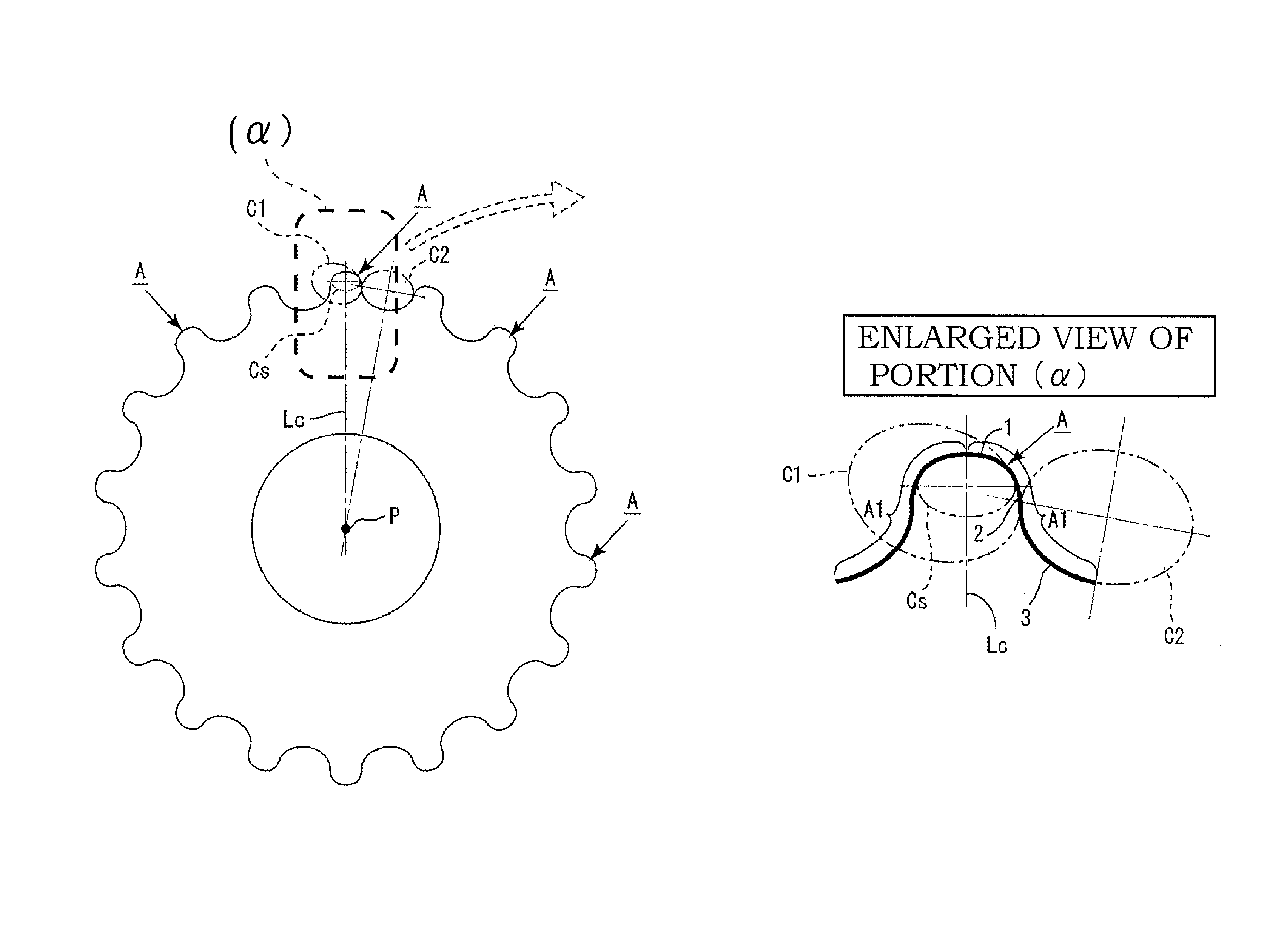
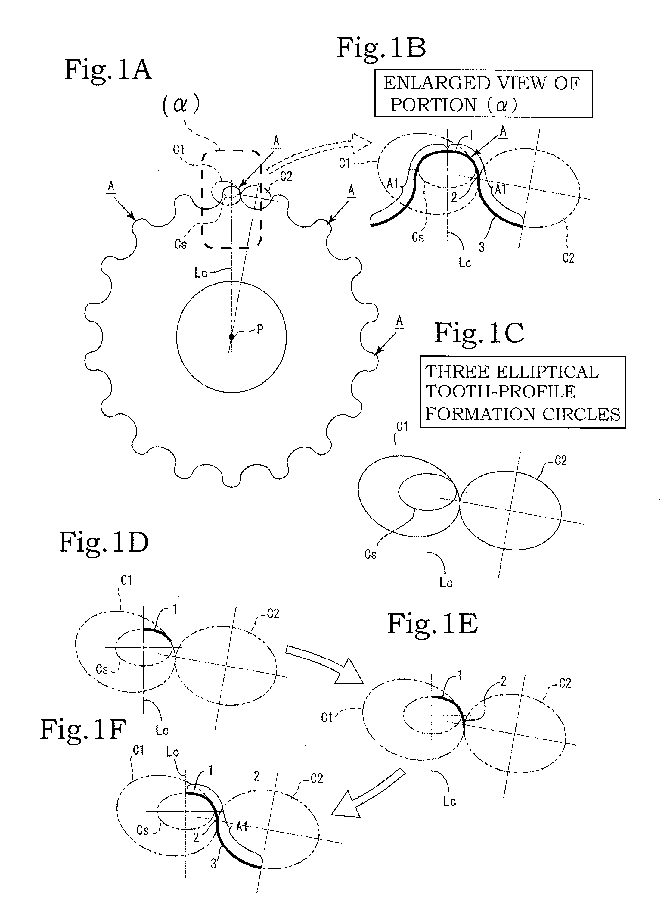
[0036]In the pump rotor according to the first aspect, it is possible to increase the number of teeth without increasing the addendum diameter, the dedendum diameter, the amount of eccentricity, that is, without increasing the tooth height, as compared to a general trochoidal rotor. Moreover, it is possible to increase a discharge amount without increasing the outer diameter or the axial thickness of the rotor.
[0037]Further, by increasing the number of teeth, it is possible to obtain a pump rotor with small pulsation and low noise. Moreover, due to the inscribing ellipse or true circle, it is possible to increase the radius of curvature near the inflection point of a connecting portion between a circular arc of the addendum and a circular arc of the engagement portion and to make the connecting portion smooth. Furthermore, since the teeth angle of the engagement portion decreases, an engagement range between the engagement portion and the outer rotor increases. As a result, it is possible to distribute the force that presses the outer rotor and to suppress the surface pressure.
[0038]Moreover, since the outer rotor is driven in a state where a rolling factor is larger than a sliding factor, the durability is improved. Since the addendum of the inner rotor and the dedendum of the outer rotor are closely situated in a small area of a deepest engagement portion, it is possible to push out oil efficiently when discharging the oil and to decrease pumping loss. Further, it is possible to decrease the noise generated when rotors engage with each other and to improve noise reduction properties. Since the pump rotor drawn according to the present invention has the same size as that of the general rotor drawn with trochoidal curves, the pump rotor according to the present invention can be easily modified to a rotor having a large theoretical discharge amount without changing the size of a rotor chamber of a housing.
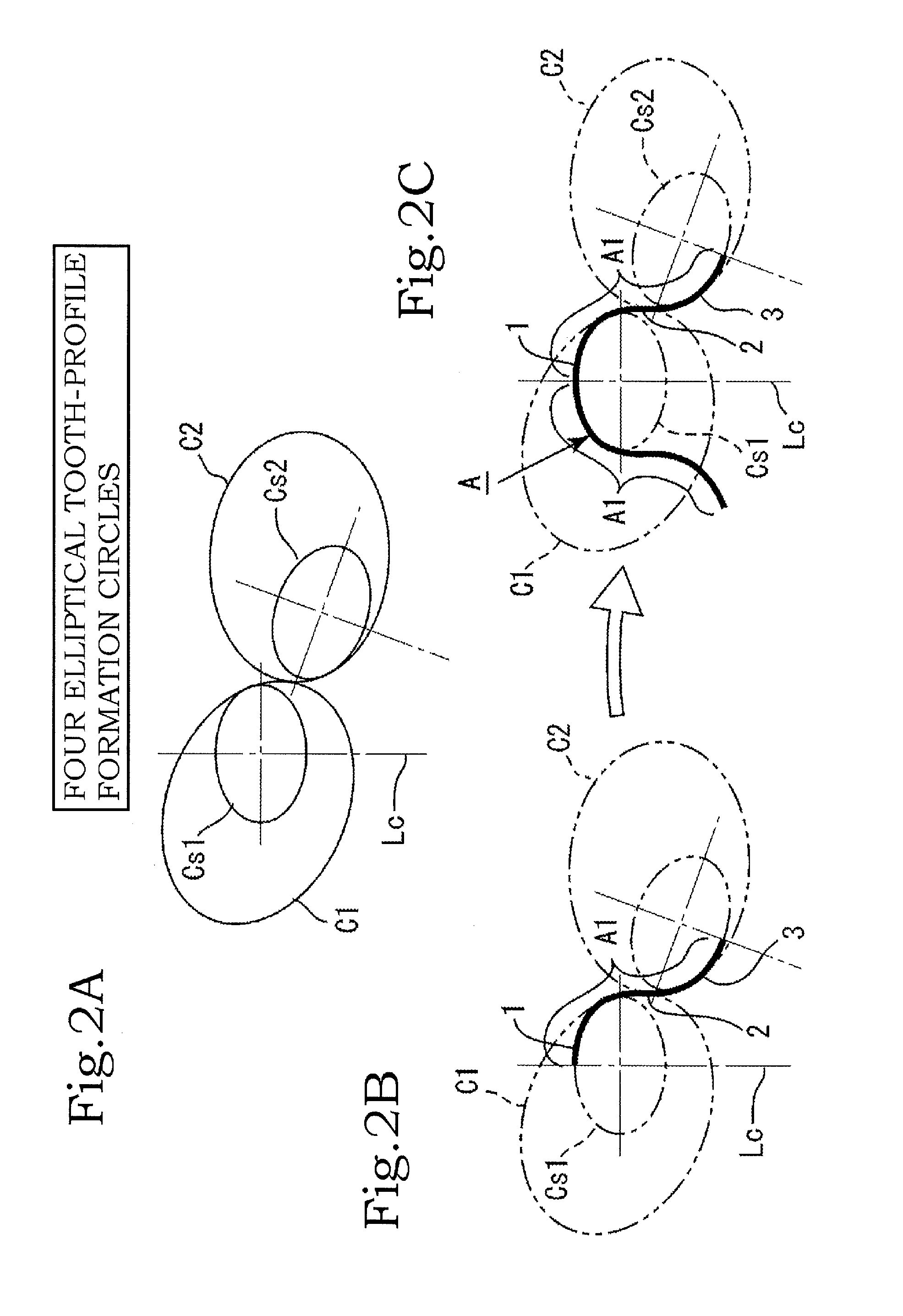
[0039]In the second invention, four tooth-profile formation circles are used, and one of the combinations of two tooth-profile formation circles includes a small tooth-profile formation circle that is included in the other tooth-profile formation circle so as to be partially in contact with each other, and a portion of the small tooth-profile formation circle forms a dedendum portion of the half-tooth portion. Therefore, it is possible to form the tooth profile with higher accuracy.
[0040]In the third aspect, since the tooth-profile formation circles are formed of a combination of ellipses only, it is possible to allow the addendum portion to have a flat shape and to obtain a tooth profile that provides satisfactory mechanical strength. In the fourth aspect, since the tooth-profile formation circles are formed of a combination of true circles only, it is possible to simplify a tooth profile forming step. In the fifth aspect, since the tooth-profile formation circles are formed of a combination of an ellipse and a true circle, it is possible to form a tooth profile with higher accuracy.

Problems solved by technology

Further, noise generated when rotors engage with each other tends to increase, and noise reduction properties are not satisfactory.

Method used


Image

  • Pump rotor
  • Pump rotor
  • Pump rotor

Examples


Embodiment Construction

[0048]Hereinafter, embodiments of the present invention will be described with reference to drawings. A pump rotor according to the present invention is a gear rotor that constitutes an internal gear pump. The pump rotor of this type generally includes a combination of an inner rotor and an outer rotor in which the inner rotor is disposed at an inner side thereof and which rotates.

[0049]The present invention mainly relates to an inner rotor of a pump rotor. Hereinafter, the inner rotor of a pump rotor will be mainly described. FIG. 5 shows a tooth profile A of the pump rotor (the inner rotor) according to the present invention as compared to a tooth profile B of a general inner rotor drawn with a trochoidal curve. The tooth profile A of the present invention and the trochoidal curve tooth profile B are disposed at the same position.

[0050]An addendum circle Ja and a dedendum circle Jb are the same between the tooth profile A of the pump rotor (the inner rotor) drawn according to the ...


PUM


Abstract

A pump rotor is an inner rotor of an internal gear pump, the inner rotor having a tooth profile, wherein a half-tooth portion of the tooth profile is formed of three tooth-profile formation circles that are elliptical or true-circular. Two of the tooth-profile formation circles are a combination of a small tooth-profile formation circle and a large tooth-profile formation circle in which the small tooth-profile formation circle is inscribed and is entirely included. A portion of the small tooth-profile formation circle forms an addendum portion of the half-tooth portion. A portion of the large tooth-profile formation circle in which the small tooth-profile formation circle is inscribed and is entirely included forms an engagement portion of the half-tooth portion. A portion of another tooth-profile formation circle that circumscribes the large tooth-profile formation circle forms a dedendum portion of the half-tooth portion.

Description

BACKGROUND OF THE INVENTION[0001]1. Field of the Invention[0002]The present invention relates to a pump rotor capable of increasing a discharge amount and improving durability without increasing an outer diameter or an axial thickness of a rotor.[0003]2. Description of the Related Art[0004]In rotors of the related art such as a trochoidal gear used in an internal gear pump such as an oil pump, the number of teeth is practically restricted by specifications such as a dedendum diameter of an inner rotor and an amount of eccentricity relative to an outer rotor. Thus, the number of teeth can be increased or decreased within a narrow range. Moreover, if the dedendum diameter, amount of eccentricity, and number of teeth described above are determined, a theoretical discharge amount is practically determined.[0005]In a trochoidal rotor of the related art, in order to increase a theoretical discharge amount, a method of increasing an amount of eccentricity between an inner rotor and an oute...

Claims


Application Information

Patent Timeline
Patent Type & Authority Patents(United States)
IPC IPC(8): F04C2/00F04C15/00F01C1/18F04C2/08F01C21/00F04C18/00F04C2/10
CPCF04C2/084F04C2/102Y10T74/19972
Inventor FUJIKI, KENICHIIZUTSU, MASATO
Owner YAMADA MANUFACTURING CO LTD
Learn More