Eureka AIR delivers breakthrough ideas for toughest innovation challenges, trusted by R&D personnel around the world.

Multi-clutch transmission for a motor vehicle

a transmission and multi-clutch technology, applied in mechanical equipment, transportation and packaging, gearboxes, etc., can solve the problems of insufficient number of gears and speed reduction ratios, inability to install the transmission into the vehicle, and less suited to heavy vehicles, etc., to achieve high power transfer, reduce production costs, and reduce the effect of production cos

Active Publication Date: 2015-08-04
VOLVO LASTVAGNAR AB
View PDF28 Cites 0 Cited by
  • Summary
  • Abstract
  • Description
  • Claims
  • Application Information

AI Technical Summary

Benefits of technology

[0003]When properly designed, dual clutch transmissions have a potential of providing powershifts at a reasonable production cost and low power losses. This is due to the fact that the rotating parts, i.e., gearwheels, shafts and tooth clutches, are similar to those in conventional stepped transmissions. This, furthermore, enables the use of the same production equipment. So, it makes sense to produce dual clutch transmissions in the same facilities as used for conventional stepped transmissions.
[0006]DE102005030987A1, DE102005033027A1 , DE102006015661 A1 and EP1624232A1 show transmission concepts where a main transmission of dual clutch type is connected in series with a range section. That makes it possible to double the number of gears and obtain gears for high tractive force as well as gears tor high vehicle speed.
[0008]DE102005050067A1 and WO2007 / 039021A1. Therein, the input and output of the transmission can be connected by a friction clutch. This friction clutch can transfer power when a gear shift takes place. Thereby, power interruption can be avoided at all gear shifts.
[0016]U.S. Pat. No. 6,958,028 B2, FIG. 5, shows a dual clutch transmission with a planetary range section. This transmission is similar to the one in U.S. Pat. No. 7,070,534 B2. The main difference is that both input shafts, 30 and 40, use the same countershaft 50, tooth clutch 130, and gearwheels 122, 124 and 126, 128 between this countershaft and the planetary range section. Power interruption between low and high range gears is eliminated by a bridge torque path via a separate countershaft 152. That makes the transmission wide, and it shares the rest of the disadvantages of the one in U.S. Pat. No. 7,070,534 B2; many components, long, and high power losses for high range gears.
[0017]In US 2008 / 0188342A1, FIG. 1 presents a single countershaft dual clutch main transmission 10 combined with a planetary range section 12. A bridge torque path is formed by a tooth clutch 84 that rotationally locks a loose gearwheel 64 on main shaft 28 to a planet carrier 68 rotationally fixed to output shaft 70. When power is led in this path, the gearwheels in the planetary range section are idling, and it can be shifted between high and low positions. This gives a narrow transmission with high reduction ratios where power interruptions can be avoided at every shift between consecutive gears. However, this bridge path embodiment has a number of drawbacks. Firstly, the tooth clutch 84 is of complex design, making it costly and long. Secondly, the bearing 32 that carries main shaft 28 must be located in front of loose gearwheel 64. This puts a large part of the main shaft 28 behind bearing 32, which, in turn, increases misalignments in the ramie section and tooth clutch 84. Moreover, the assembly of the transmission is not facilitated by a main shaft having gearwheels and tooth clutches on both, sides of the housing wall that carries bearing 32.
[0020]Thus, for heavy, on- and off-road vehicles there is a need for a transmission that i) enables high power transfer to the driven wheels during all shifts between consecutive gears, it) can provide high reduction ratios, iii) is cost-effective and simple to produce, iv) has low power losses and v) can be installed in a vehicle where the space available, especially axially, is limited.

Problems solved by technology

That may lead to difficulties in installing the transmission into the vehicle.
The number of gears and the speed reduction ratios possible are insufficient for heavy duty vehicles, though.
These concepts are, hence, less suited to heavy vehicles.
Unfortunately, there are shifts between consecutive gears where the power transfer will be interrupted in these designs.
That is not an option for heavy on- and off road vehicles subjected to high driving resistance.
However, for reasonable sizes of this friction clutch, the power transferred to the driven wheels is very small at shifts between low gears.
Thus, these types of dual clutch transmission would have a limited practical use, especially for on- and off-road vehicles.
This would probably be acceptable on most heavy on-road vehicles, but not for, e.g., trucks in hilly applications or articulated haulers.
That limits the practically possible speed reduction.
Thereby, these transmissions are not suited to heavy vehicles.
However, the transmission is both wide and long due to two parallel countershafts and a large number of gearwheels located, side by side.
That makes the transmission incompatible with most heavy truck designs.
The number of components is large, adding costs.
Unfortunately, the number of rotating components, e.g., gearwheels and tooth clutches, is relatively large in comparison with the number of gears.
Thereby, it will be difficult to fit in the vehicle.
The transmission will be costly to manufacture due to the large number of components.
Furthermore, the idling planetary range section will imply unnecessarily large power losses in high range gears.
Hence, there are several disadvantages that make this transmission less suited for use in heavy vehicles.
That makes the transmission wide, and it shares the rest of the disadvantages of the one in U.S. Pat. No. 7,070,534 B2; many components, long, and high power losses for high range gears.
However, this bridge path embodiment has a number of drawbacks.
Firstly, the tooth clutch 84 is of complex design, making it costly and long.
Moreover, the assembly of the transmission is not facilitated by a main shaft having gearwheels and tooth clutches on both, sides of the housing wall that carries bearing 32.
Thirdly, adding parts for tooth clutch 84 will make the already complex shape of planet carrier 68 even more complex and tricky to produce. FIG. 3 shows a similar dual, clutch main transmission in combination with a non-planetary range section 102.
However, these transmissions are of conventional type, having a single frictional master clutch and power interruption at every gear shift.
This limits their use to on-road, non-severe heavy vehicle applications.

Method used


Image

  • Multi-clutch transmission for a motor vehicle
  • Multi-clutch transmission for a motor vehicle
  • Multi-clutch transmission for a motor vehicle

Examples


Embodiment Construction

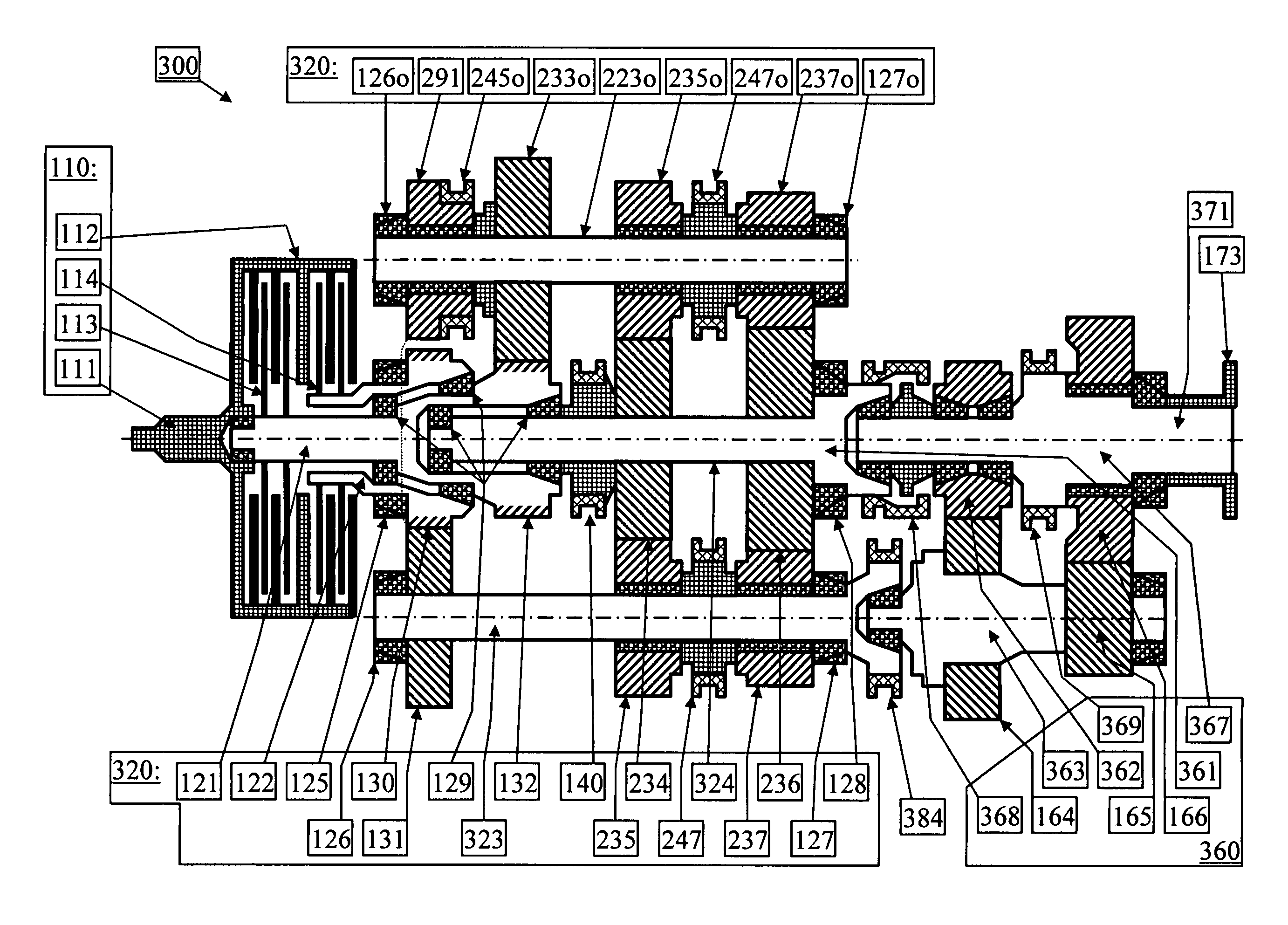
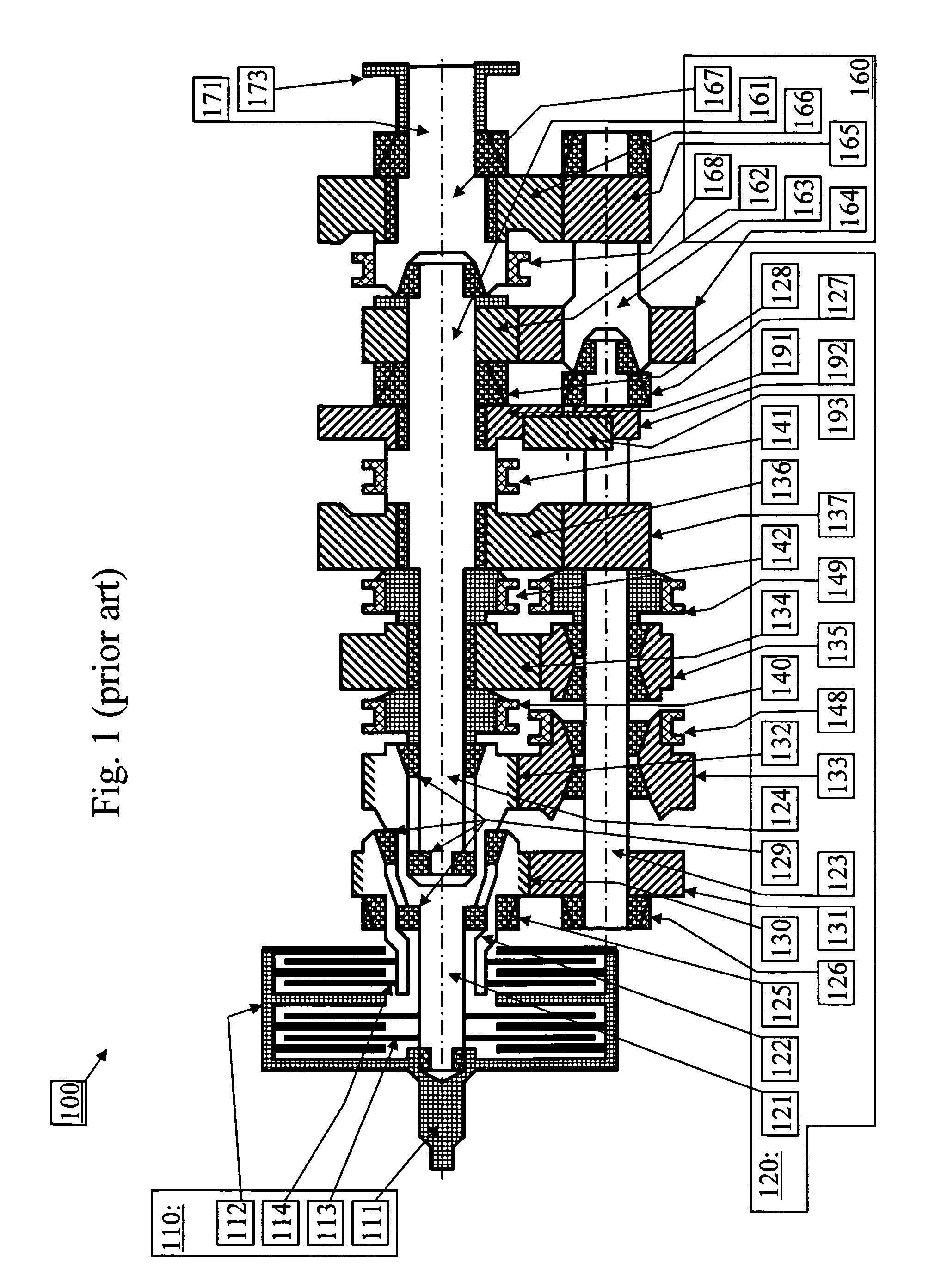
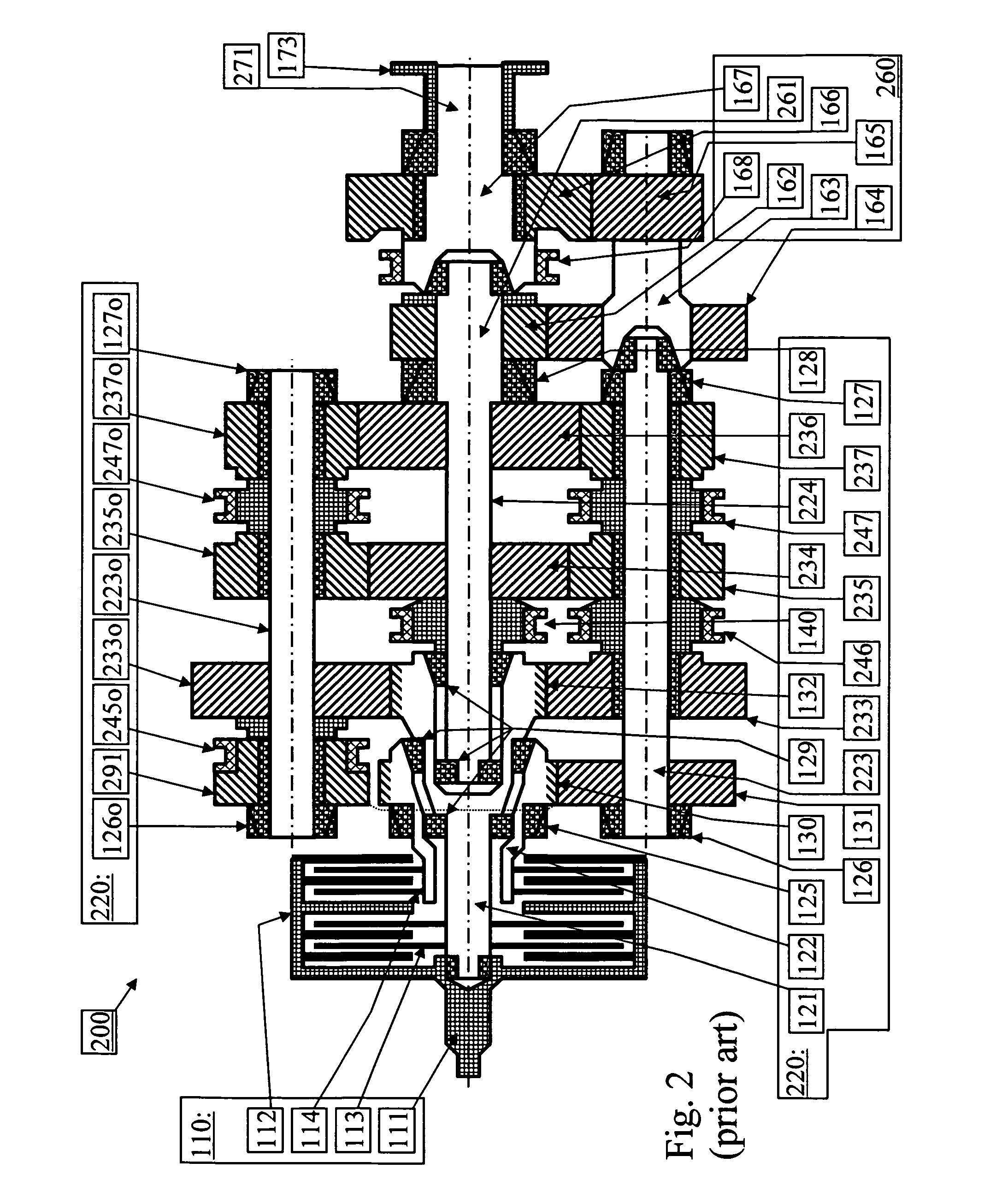
[0028]FIG. 1 shows schematically a longitudinal section the rotating parts of a transmission 100 for a heavy vehicle. The transmission 100 is composed of a dual frictional clutch unit 110, a main transmission 120 of dual clutch transmission type, and a range section 160 of non-planetary type. The dual frictional clutch unit 110 comprises a clutch input shaft 111 driven by an engine crankshaft (not shown), a clutch assembly 132 connected thereto, featuring first and second sub-clutches 113, 114, and an actuator device (not shown) to control the clutch unit.

[0029]The main transmission 120 has two input shafts; a first input shaft 121 and a second input shaft 122. The first input shaft 121 can be rotationally driven by the first sub-clutch 113. Similarly, the second input shaft 122 can be rotationally driven by the second sub-clutch 114.

[0030]A first primary gearwheel 132 is rotationally fixed or integral with the first input shaft 121. A second primary gearwheel 130 is rotationally fi...


PUM


Abstract

A multi-clutch transmission for a motor vehicle with a prime mover has a main transmission, a range section and an output shaft, the main transmission including one input shaft, a main shaft and a main countershaft, the main shaft being rotationally fixed with a range input shaft of the range section, the range section including a range main shaft that is rotationally fixed with the output shaft, a range countershaft, range gearwheels that can selectively transfer power from the range input member to the range countershaft and on to the range main shaft, and range clutches, the multi-clutch transmission including a by-passing torque path in which power can be transferred when the range section is shifted, and where the by-passing torque path includes a by-passing clutch that selectively can rotationally lock the main countershaft to the range countershaft.

Description

BACKGROUND AND SUMMARY[0001]The present invention relates to vehicle transmissions, especially for heavy, on- and off-road vehicles, and more particularly to dual- and multi-clutch transmissions with a range section that, as set out in the preamble of claim 1 and as disclosed in U.S. Pat. No. 5,511,437.[0002]Dual clutch transmissions are a cross-breed between conventional stepped transmissions, with power interruption at gear shifts, and powershifting, without power interruption, planetary transmissions. In principle, a dual clutch transmission has two input shafts, each connectable to a friction clutch and to the output of the engine. Functionally, this is equivalent to having two conventional transmissions in parallel, i.e., two parallel sub-transmissions, and using one at a time for poller transfer. The sub- transmission that is not used, idling, for the time being! can have a gear engaged and prepared for a subsequent shift. This shift is carried out by simultaneously disengagin...

Claims


Application Information

Patent Timeline
Patent Type & Authority Patents(United States)
IPC IPC(8): F16H3/08F16H37/04F16H3/00F16H3/097F16H3/087F16H61/04
CPCF16H3/097F16H3/006F16H37/043F16H3/087F16H2200/0052F16H2200/0078F16H2061/0429Y10T74/19233
Inventor HEDMAN, ANDERSSTALBERG, DANIEL
Owner VOLVO LASTVAGNAR AB
Why Eureka
Eureka Blog
Learn More