Radiating cell having two phase states for a transmitting network

Active Publication Date: 2015-08-04
COMMISSARIAT A LENERGIE ATOMIQUE ET AUX ENERGIES ALTERNATIVES
View PDF11 Cites 8 Cited by
  • Summary
  • Abstract
  • Description
  • Claims
  • Application Information

AI Technical Summary

Benefits of technology

The invention provides a planar antenna that has two surfaces that work together to create an efficient excitation of the antenna. One surface is connected to a radiating element, while the other surface has conducting zones that help to pick up incident signals. A switching means is arranged at the interface between the two surfaces. The invention also includes a ground plane that is connected to the radiating element and a control conducting line that can transport electric current to polarize the switching means. This makes it easy to control the breakers. The technical effects of the invention include improved efficiency of the antenna, simplified design, and easy control of the breakers.

Problems solved by technology

However, a drawback of this cell is its narrow passband (of the order of a few percent), which is a direct consequence of the use of the coupling technique, which relies on resonators necessarily having a frequency dispersion of significant phase.
However, the implementation of such a transmitter array is complicated since it requires non-integrated phase shifters, which are therefore of large dimensions, connected perpendicularly to the plane of the antennas.
However, the experimental results have revealed several drawbacks:a significant level of loss of the order of 3 dB and varying in an appreciable manner as a function of the transmission phase;a narrow passband due to the use of resonators;a high number of components and complicated means of control of the components, the control lines having to be connected to the radiating elements, so giving rise, moreover, to appreciable perturbations.

Method used


Image

  • Radiating cell having two phase states for a transmitting network
  • Radiating cell having two phase states for a transmitting network
  • Radiating cell having two phase states for a transmitting network

Examples


first embodiment

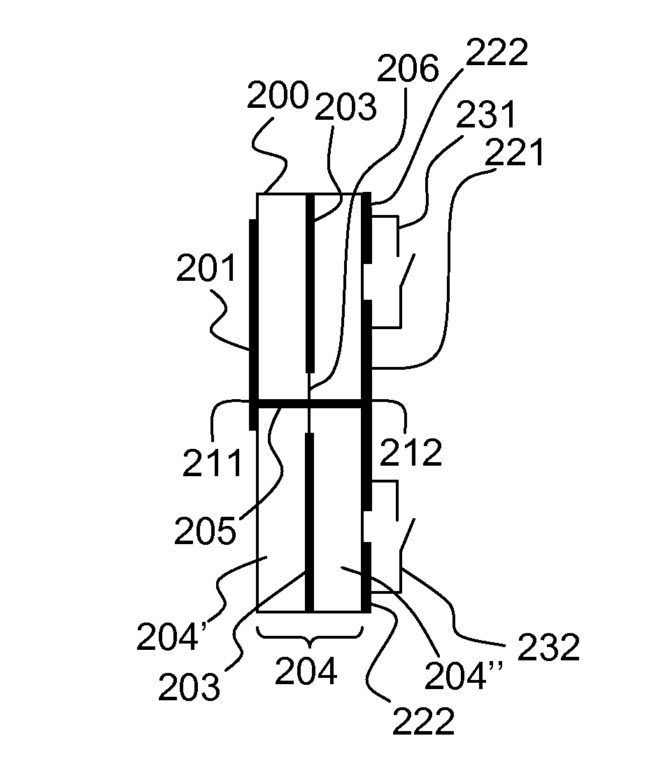
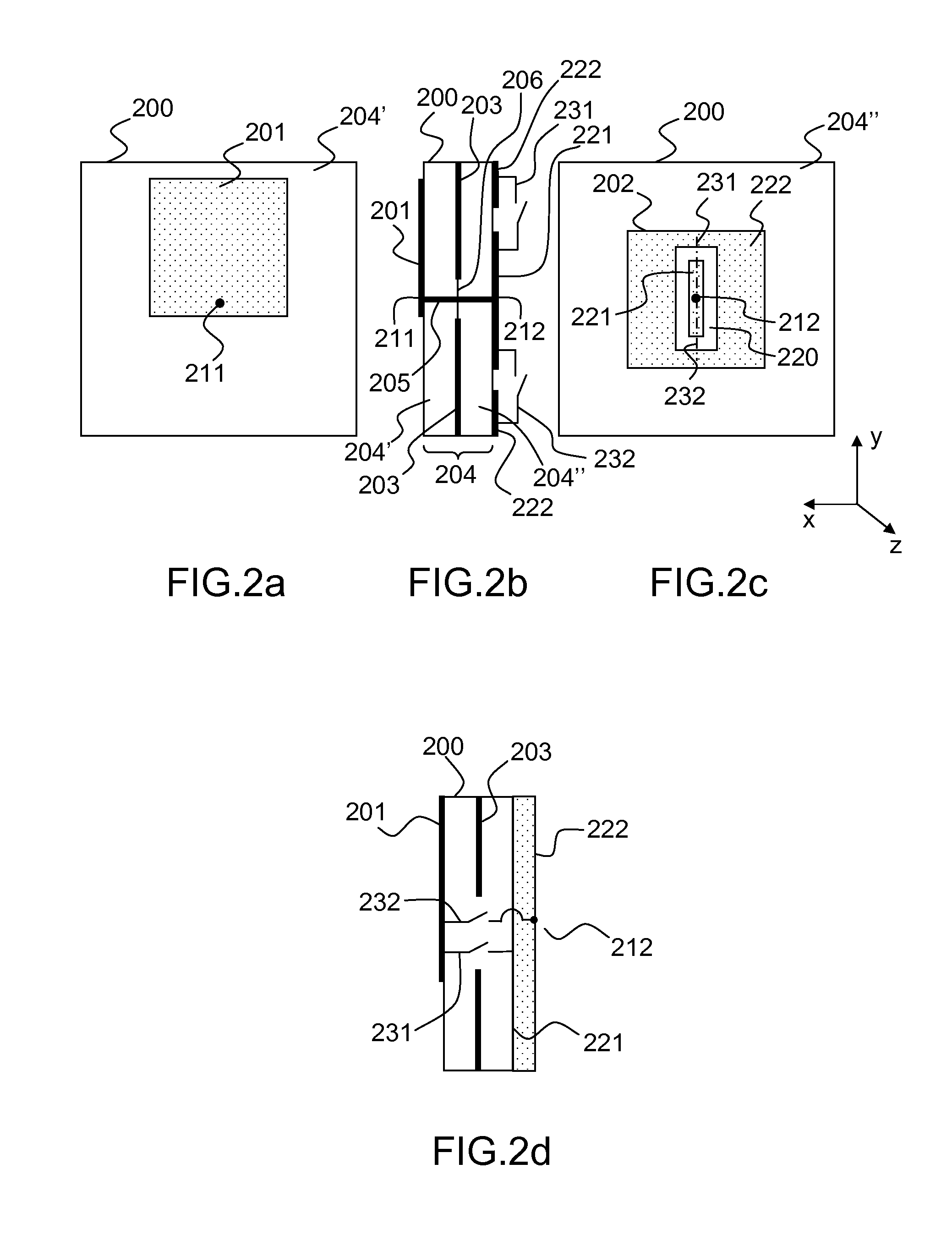
[0064]FIGS. 2a, 2b, 2c and 2d present a cell according to the invention. FIG. 2a is a view from below of the cell 200, FIGS. 2b and 2d are a cross-sectional view of the cell 200 and of its variant respectively, and FIG. 2c is a view from above of the cell 200.

[0065]In this example, the cell 200 comprises two elementary antennas arranged on either side of a ground plane 203.

[0066]More particularly, if it is considered that an elementary antenna comprises a radiating element separated by the ground plane from at least one dielectric layer, the cell 200 therefore comprises a first radiating element 201 and a second radiating element 202 arranged on either side of the ground plane 203 hugged in an assemblage 204 of at least two substrates (or substrate-forming dielectric layers) 204′, 204″.

[0067]Each elementary antenna can be embodied by a planar or patch antenna which is a plane antenna whose radiating element is a generally square conducting surface, separated from a conducting reflec...

second embodiment

[0105]A second embodiment is illustrated in FIGS. 3a, 3b and 3c.

[0106]FIG. 3a is a view from below of the cell 300, FIG. 3b is a cross-sectional view of the cell 300, and FIG. 3c is a view from above of the cell 300.

[0107]In the example of FIGS. 3a, 3b and 3c, the connection point 311 of the first radiating element 301 is situated at the center of the surface of this element 301, so as to minimize the bulk of the cell, since the two radiating elements 301, 302 lie face to face.

[0108]In order to ensure satisfactory operation of the first radiating element 301, a U-shaped slot 320 is formed around the connection point 311, in such a way that the connection point 311 is situated on a conducting band 341 formed inside the U, this conducting band 341 culminating at the level of the periphery 361 of the first radiating element 301. The conducting band 341 therefore acts as a conduction line making it possible to efficiently excite the first radiating element 301 at the level of its perip...


PUM


Abstract

A radiating cell having two phase states suitable for a transmitter array able to transmit microwave frequency signals, the cell comprising a first antenna and a second antenna arranged on either side of an assembly comprising two substrate layers separated by a ground plane, the second antenna comprising a conducting element able to radiate, the cell comprising comprises at least two switching means, said means each comprising an on state and an off state between two ports, one of said ports being connected to the second radiating element, said switching means being controlled in opposition. The radiating cell applies notably to the implementation of transmitter arrays employing several configurable cells to control the radiation pattern.

Description

CROSS-REFERENCE TO RELATED APPLICATIONS[0001]This application is a National Stage of International patent application PCT / EP2011 / 073565, filed on Dec. 21, 2011, which claims priority to foreign French patent application No. FR 1061253, filed on Dec. 24, 2010, the disclosures of which are incorporated by reference in their entirety.FIELD OF THE INVENTION[0002]The present invention relates to a radiating cell having two phase states and able to implement an array antenna or a lens antenna. It applies notably to the implementation of transmitter arrays employing several configurable cells to control the radiation pattern of the antenna.BACKGROUND[0003]Transmitter array antennas, sometimes designated by the term “transmit-array antenna”, are commonly used in the 1-100 GHz frequency domain for focusing a radiation; for this reason, they are therefore often also called discrete-lens antennas.[0004]Array antennas of such a type comprise a large number of individual radiating cells able to ...

Claims


Application Information

Patent Timeline
IPC IPC(8): H01Q1/38H01Q3/46H01Q21/00H01Q3/24
CPCH01Q3/46H01Q21/0018H01Q3/247
Inventor DUSSOPT, LAURENTCLEMENTE, ANTONIO
Owner COMMISSARIAT A LENERGIE ATOMIQUE ET AUX ENERGIES ALTERNATIVES
Why Eureka
Try Eureka