Wireless power feeding system

a power feeding system and wireless technology, applied in electric power, electric vehicles, transportation and packaging, etc., can solve the problems of reducing the efficiency of power transmission, difficult to stably transmit power with high efficiency,

Inactive Publication Date: 2015-08-04
SEMICON ENERGY LAB CO LTD
View PDF146 Cites 16 Cited by
  • Summary
  • Abstract
  • Description
  • Claims
  • Application Information

AI Technical Summary

Benefits of technology

[0011]In view of the foregoing, an object of one embodiment of the present invention is to provide a wireless power feeding system using the resonance method, which can increase power transmission efficiency.
[0016]One embodiment of the present invention can provide a wireless power feeding system in which the impedance of a load is adjusted by external control, so that power feeding appropriate to the situation is achieved under conditions for the maximum power transmission efficiency regardless of positional relationship, between a power transmission resonance coil in a power-transmitting device and a power reception resonance coil in a power-receiving device.

Problems solved by technology

Further, the conditions for high efficiency of power transmission vary depending on the distance between a power transmission resonance coil in a power-transmitting device and a power reception resonance, coil in a power-receiving device (hereinafter also called coil-to-coil distance), making it difficult to stably transmit power with high efficiency.
Therefore, magnetic resonance wireless power feeding, which is seemingly less spatially limited as long as the coil-to-coil distance is short, is, in reality, problematic in that the power transmission efficiency dramatically decreases when strong magnetic coupling between the coils occurs.

Method used


Image

  • Wireless power feeding system
  • Wireless power feeding system
  • Wireless power feeding system

Examples


embodiment 1

[0028]This embodiment describes a wireless power feeding system according to one embodiment of the present invention, which achieves wireless power feeding by the resonance method.

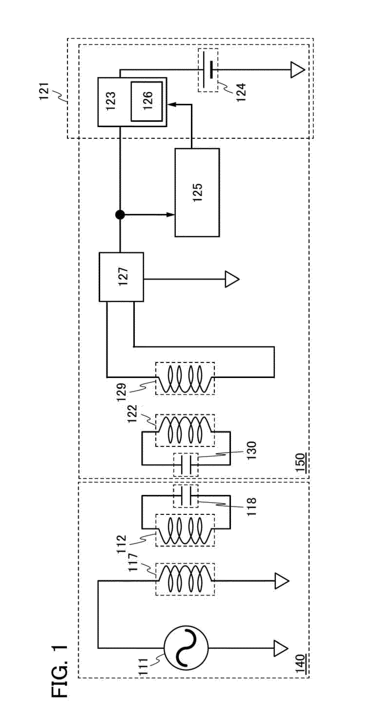
[0029]FIG. 1 illustrates a configuration of a wireless power feeding system according to one embodiment of the present invention. The wireless power feeding system in FIG. 1 uses the magnetic resonance type power transmission method. The wireless power feeding system in FIG. 1 includes a power-transmitting device 140 and a power-receiving device 150. In FIG. 1, power feeding can be achieved by electromagnetic waves when a power transmission resonance coil 112 in the power-transmitting device 140 and a power reception resonance coil 122 in the power-receiving device 150 are in resonance with each other.

[0030]The power-transmitting device 140 includes a high-frequency power supply 111, a power transmission resonance coil 112, a power transmission coil 117, and a capacitor 118. In the power-transmitting devic...

embodiment 2

[0050]This embodiment describes a configuration of a wireless power feeding system that is partly different from that in FIG. 1.

[0051]FIG. 3 illustrates a configuration of a wireless power feeding system according to one embodiment of the present invention. A power-transmitting device 160 is the same as the power-transmitting device in FIG. 1 in that it includes a high-frequency power supply 111; a power transmission resonance coil 112, a power transmission coil 117, and a capacitor 118. The power-transmitting device 160 is different from the power-transmitting device in FIG. 1 in that it includes an antenna 113, a microprocessor 115 connected to the high-frequency power supply 111, and a first transmission / reception circuit 119 connected to the microprocessor 115 and the antenna 113.

[0052]A power-receiving device 170 is the same as the power-receiving device in FIG. 1 in that it includes a load 121, a power reception resonance coil 122, a microprocessor 125, a rectifier circuit 127...

embodiment 3

[0069]This embodiment describes a configuration of a wireless power feeding system that is partly different from those in FIG. 1 and FIG. 3.

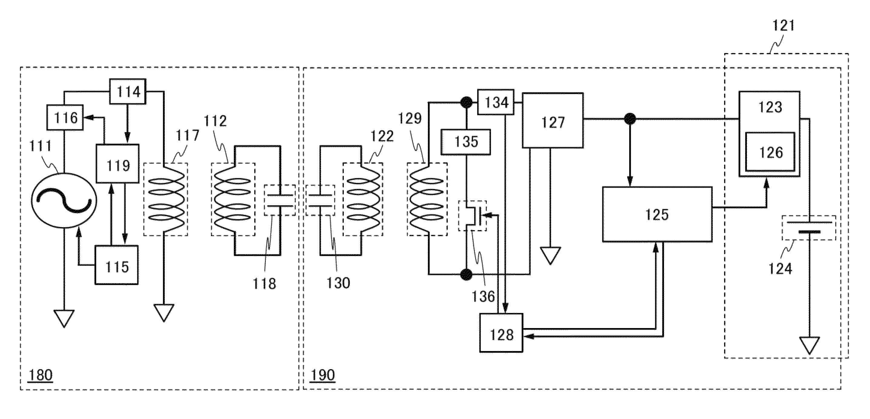
[0070]FIG. 5 illustrates a configuration of a wireless power feeding system according to one embodiment of the present invention. A power-transmitting device 180 is the same as the power-transmitting device in FIG. 3 in that it includes a high-frequency power supply 111, a power transmission resonance coil 112, a microprocessor 115, a power transmission coil 117, a capacitor 118, and a first transmission / reception circuit 119. The power-transmitting device 180 is different from the power-transmitting device in FIG. 3 in that it includes a directional coupler 114 and a mixer 116, in that the high-frequency power supply 111 is connected to the mixer 116 and the microprocessor 115, in that the first directional coupler 114 is connected to the mixer 116, the first transmission / reception circuit 119, and the power transmission coil 117, and in that t...


PUM


Abstract

An object is to provide a wireless power feeding system using the resonance method, which can increase power transmission efficiency. The wireless power feeding system includes a power transmission coil electrically connected to a high-frequency power supply, a power transmission resonance coil for transmitting power by electromagnetic induction with the power transmission coil, a power reception resonance coil for exciting high-frequency power by magnetic resonance, a load coil for exciting high-frequency power by electromagnetic induction with the power reception resonance coil, a load, and a variable element. The load includes a microprocessor for controlling the impedance of the load, a battery charger, and a battery. The battery charger is configured to charge the battery with the high-frequency power excited by the load coil.

Description

BACKGROUND OF THE INVENTION[0001]1. Field of the Invention[0002]The present invention relates to a wireless power feeding system including a power-receiving device.[0003]2. Description of the Related Art[0004]A method called a magnetic resonance method attracts, attention as a method for feeding power to an object (hereinafter also called a power-receiving device) not in contact with a power supply (hereinafter also called a power-transmitting device) (such a method is also called a contactless power feeding method, a wireless power feeding method, or the like). The magnetic resonance method is a method in which resonance coils provided in a power-transmitting device and a power-receiving device are put in magnetic resonance with each other to form an energy propagation path. The magnetic resonance method yields a longer power transmittable distance than other methods (e.g., an electromagnetic induction method and a field induction method). For example, Non-Patent Document 1 disclos...

Claims


Application Information

Patent Timeline
Patent Type & Authority Patents(United States)
IPC IPC(8): H02J7/00H02J7/02H02J7/04
CPCH02J7/025H02J7/045H02J50/12H02J50/80H02J7/04H02J7/007182H02J50/90
Inventor KAMATA, KOICHIRO
Owner SEMICON ENERGY LAB CO LTD
Why Eureka
Try Eureka