
Auto-heterodyne receiver

a receiver and auto-heterodyne technology, applied in the field of receiver circuits, can solve the problems of insufficient precise direct phase measurement by means of monodyne receivers, difficult in principle precise measurement of phase shifts, and limited stability of such conversions, so as to reduce circuitry demands

Inactive Publication Date: 2015-08-04
FORSCHUNGSVERBUND BERLIN EV
View PDF14 Cites 0 Cited by
  • Summary
  • Abstract
  • Description
  • Claims
  • Application Information

AI Technical Summary

Benefits of technology

Enables precise phase angle measurement and amplitude determination of high-frequency signals, reducing the impact of frequency fluctuations and allowing for accurate active power calculation and efficient signal processing, particularly suitable for plasma-based processes and communication engineering applications.

Problems solved by technology

With high-frequency signals, an exact measuring of phase shifts is difficult in principle since a very high time resolution of the very short period of the high-frequency signals would be necessary therefor.
However, such a plasma load may be very reactive so that the phase angle between current and voltage may be nearly 90°.
However, the phase angle has to be measured very precisely in order to be able to calculate active power correctly since even the slightest errors of measurement have a superproportional effect on the determination of active power.
For such a task, a direct phase measurement by means of a monodyne receiver is not precise enough, which is why, e.g., heterodyne receivers or samplers are used for measurement.
However, the limited stability of such a conversion is problematic.
Moreover, the difficulty of conversion increases with an increasing original-frequency / intermediate-frequency ratio.
Therefore, prior-art approaches do not allow particularly low intermediate frequencies in the high-frequency range provided for the invention.

Method used


Image

  • Auto-heterodyne receiver
  • Auto-heterodyne receiver
  • Auto-heterodyne receiver

Examples


Embodiment Construction

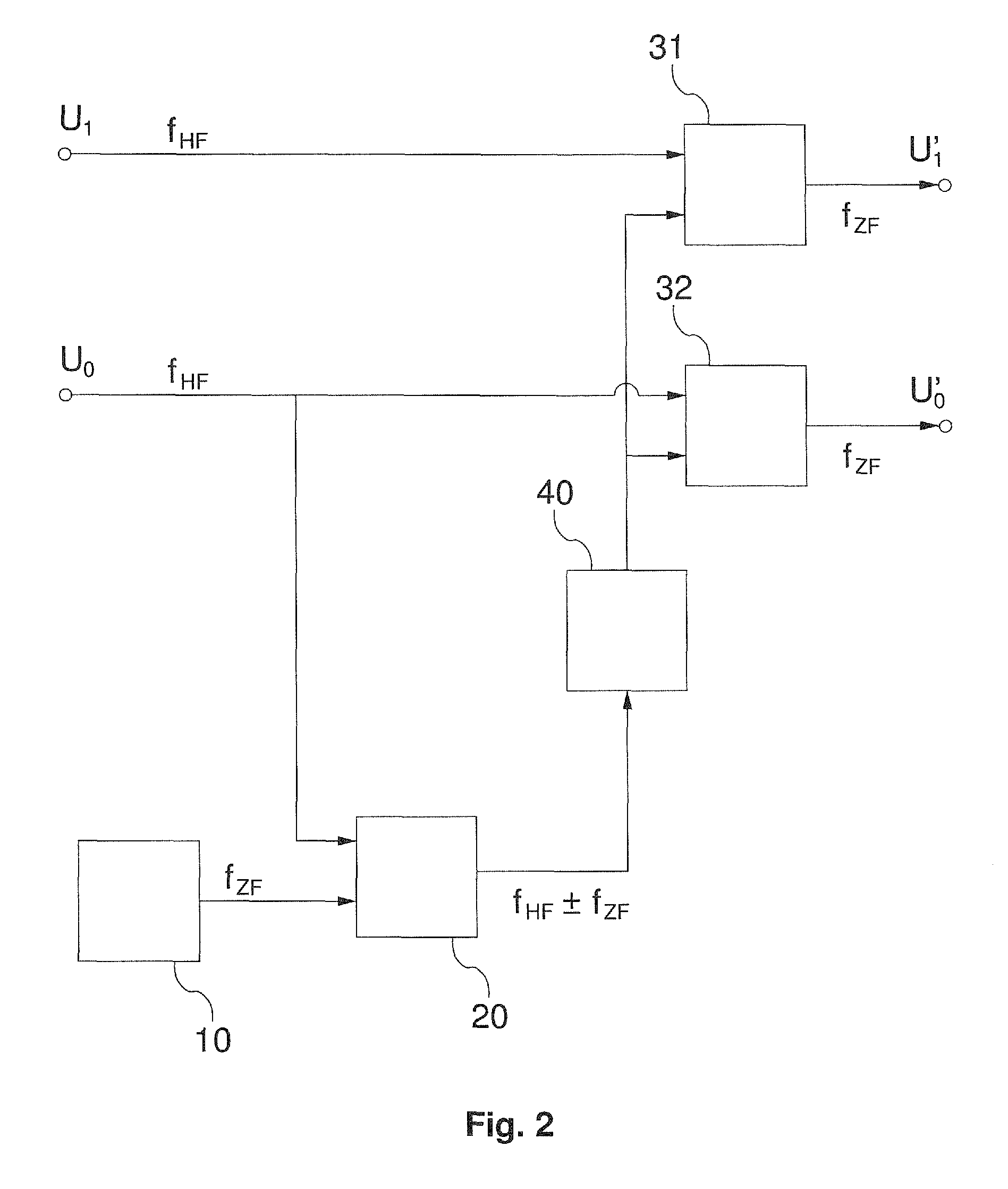
[0022]In the following, the invention will be explained in greater detail on the basis of two figures of exemplary embodiments.

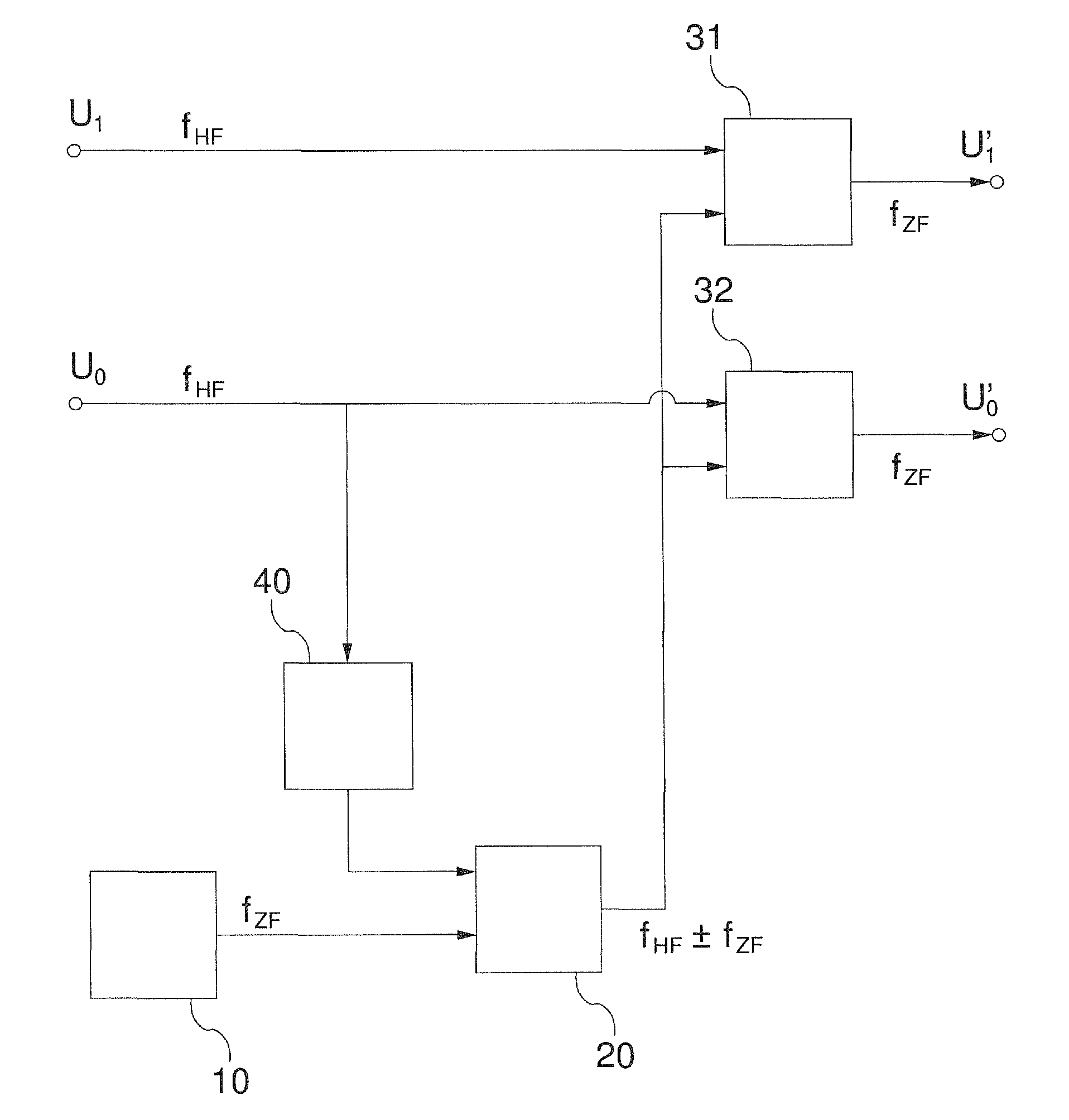
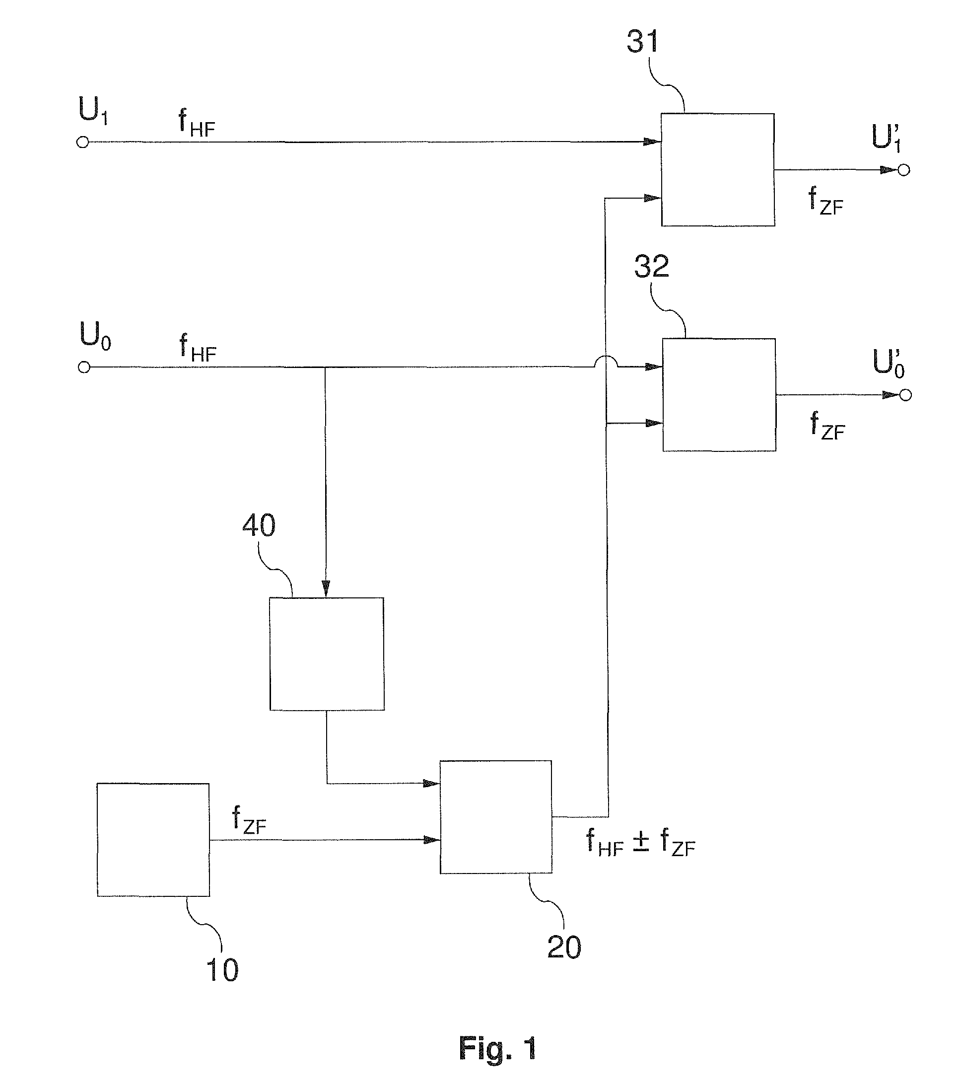
[0023]FIG. 1 shows a first exemplary embodiment of an inventive receiver circuit in the form of a block diagram. Input signals U0 and U1 having a frequency fHF are present at two signal inputs of the receiver circuit. The two input signals may be two voltage signals, wherein one of the voltage signals is derived from a current that is operatively connected to the other voltage signal. An active-power / reactive-power ratio can then be determined by measuring the phase angle between the two input signals.

[0024]Any of the two input signals is transferred to an input of a quadrature modulator 20, wherein the selected input signal is advantageously led through an amplitude normalization unit 40 designed to amplify / damp the selected input signal up / down to a predetermined amplitude. An oscillation signal generated by a local oscillator 10 is transferred to the seco...


PUM


Abstract

A receiver with a local oscillator, a quadrature modulator, a first mixer and a second mixer, wherein a first input of the quadrature modulator is connected to a second signal input of the receiver circuit and a second input of the quadrature modulator is connected to the local oscillator. Further, a first input of the first mixer is connected to a first signal input of the receiver circuit, a second input of the first mixer is connected to an output of the quadrature modulator, and an output of the first mixer is connected to a first signal output of the receiver circuit. A first input of the second mixer is connected to the second signal input, a second input of the second mixer is connected to the output of the quadrature modulator, and an output of the second mixer is connected to a second signal output of the receiver circuit.

Description

CROSS-REFERENCE TO RELATED APPLICATIONS[0001]This application is a §371 national phase filing of PCT / EP2012 / 057537 filed Apr. 25, 2012, which claims priority to and the benefit of DE 10 2011 017 545.8 filed Apr. 26, 2011, both of which are herein incorporated by reference in their entirety.TECHNICAL FIELD[0002]The invention relates to a receiver circuit and to a measuring device for measuring high-frequency signals with such a receiver circuit.PRIOR ART[0003]With high-frequency signals, an exact measuring of phase shifts is difficult in principle since a very high time resolution of the very short period of the high-frequency signals would be necessary therefor. In many applications, however, an exact measuring of the present phase shift is necessary, which is important, e.g., with respect to plasma generation for plasma-based processes, e.g., plasma etching or surface treatment, where the HF or microwave power outputted to the plasma load is to be measured for controlling the proce...

Claims


Application Information

Patent Timeline
Patent Type & Authority Patents(United States)
IPC IPC(8): H04B17/00G01S5/04H04B17/21G01S3/48G01S3/46
CPCH04B17/0062H04B17/21G01S3/48G01S3/46
Inventor KUHN, SILVIOGESCHE, ROLAND
Owner FORSCHUNGSVERBUND BERLIN EV
Learn More