Method and device for blow molding containers

Active Publication Date: 2015-08-11
KHS GMBH
View PDF15 Cites 3 Cited by
  • Summary
  • Abstract
  • Description
  • Claims
  • Application Information

AI Technical Summary

Benefits of technology

The present invention aims to improve the method of blow molding containers by using inexpensive machinery to produce high-quality containers with high throughput rates. The device is designed to have a simple construction and good product quality. The control or regulation of the blow molding process takes into consideration various parameters and interactions to maintain desired values and prevent harmful influences. The simulation model of the blow molding process takes into consideration various factors to predict the properties of the blow molded container, allowing for quick regulation of problems and prevention of containers with undesired properties from being produced.

Problems solved by technology

In particular, the control of the actual blowing pressure has been found to be difficult because, between a control valve for presetting the blowing pressure and the preform to be expanded, there is a flow path with different cross-sectional sizes of the lines and throttles which influence the flow and, moreover, the volume increase of the preforms during the deformation into the container causes a return reaction to the pressure which is generated.
On the other hand, moving the stretching rod into the preform results in a reduction of the available volume.
Moreover, there are relatively complex interactions between individual parameters which influence the concrete actual material distribution in the blow molded container.
Actually realized regulations typically refer to individual parameters, without sufficiently taking into consideration the complexity of the blow molding process.
Moreover, the existing regulation concepts have, because of the complex interactions between the individual blow molding parameters, weaknesses occur which lead to regulations of deviations which are not satisfactory or result in long regulation times.

Method used


Image

  • Method and device for blow molding containers
  • Method and device for blow molding containers
  • Method and device for blow molding containers

Examples


Embodiment Construction

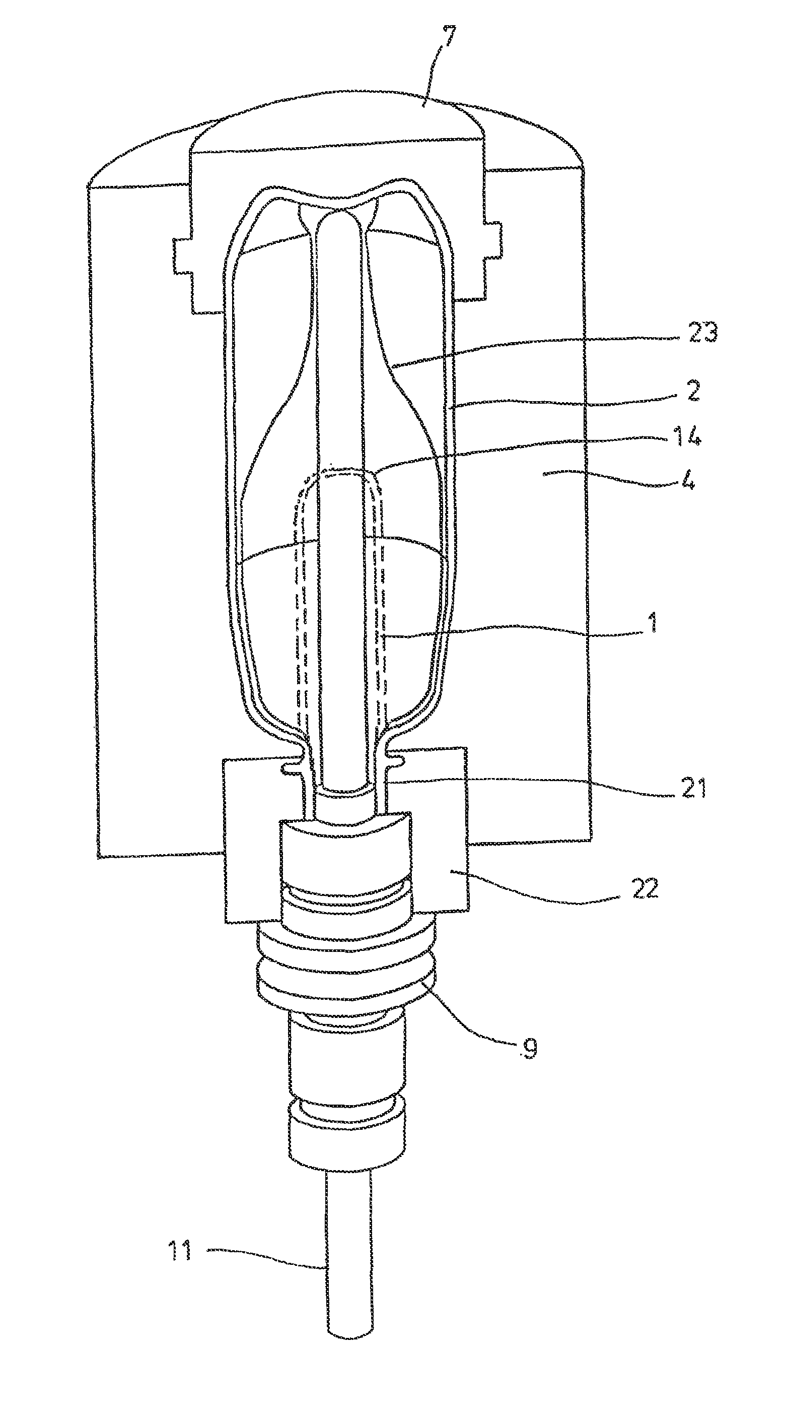
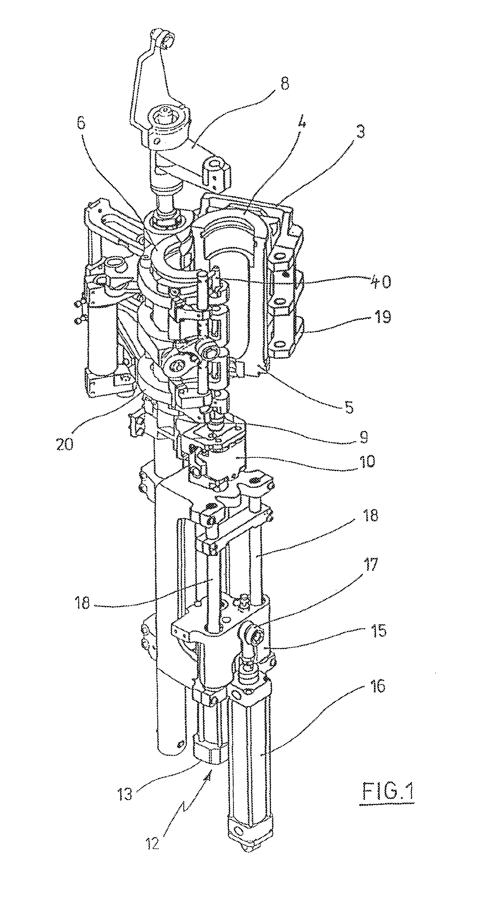
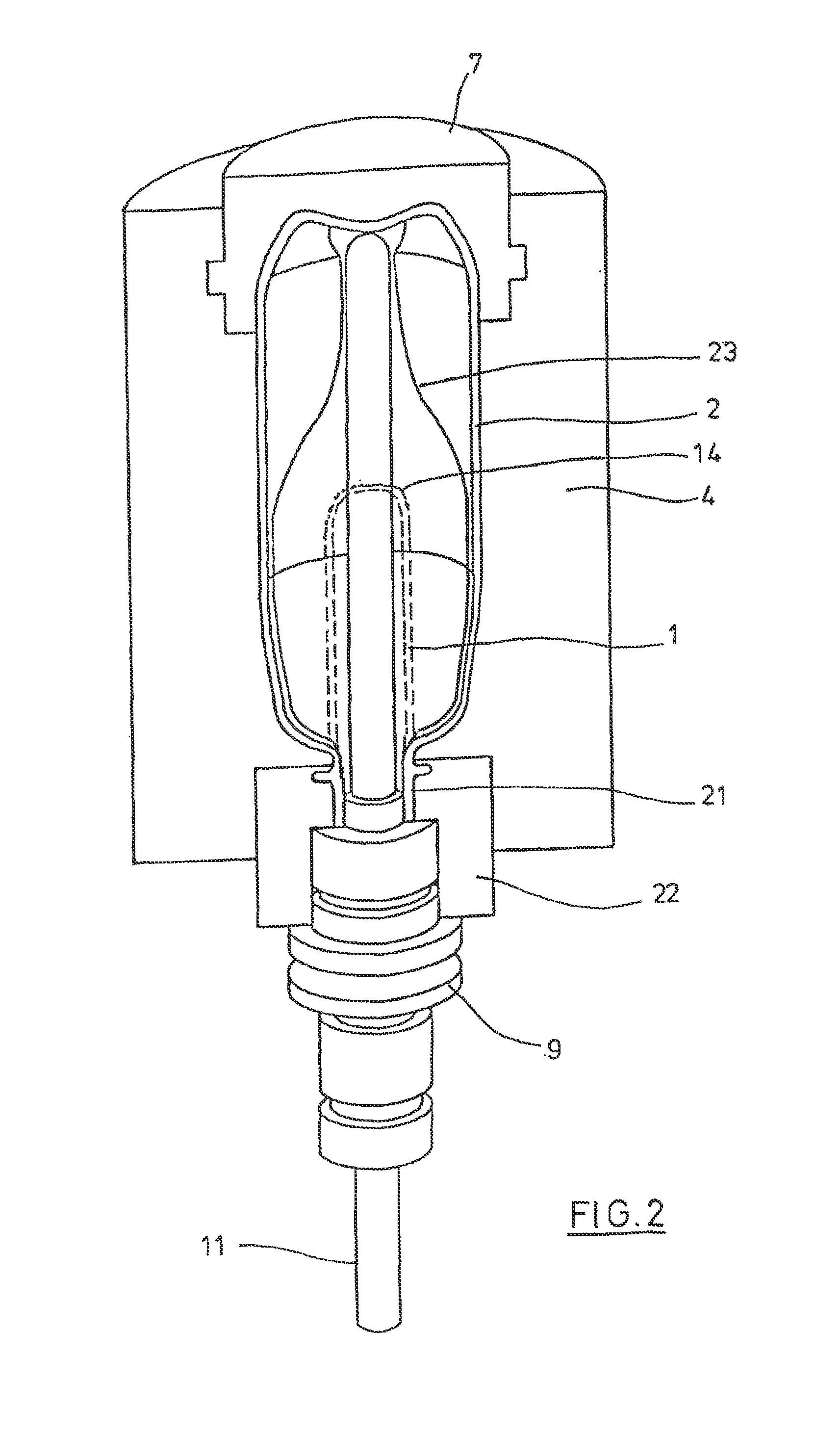
[0040]The principal construction of a device for deforming preforms 1 into containers 2 is illustrated in FIG. 1 and FIG. 2.

[0041]The device for forming the container 2 consists essentially of a blow molding station 3 which is provided with a blow mold 4 into which a preform 1 can be placed. The preform 1 may be an injection molded part of polyethylene terephthalate. For facilitating a placement of the preform 1 into the blow molds 4 and for facilitating a removal of the finished containers 2, the blow mold 4 is composed of mold halves 5, 6 and a bottom part 7 positioned by means of a lifting device 8. The preform 1 can in the area of the blow station 3 be held by a transport mandrel 9 which, together with the preform 1, travels through a plurality of treatment stations within the device. However, it is also possible to place the preform 1 directly into the blow mold 4 through tongs or other manipulating means.

[0042]For facilitating a compressed air supply, underneath the transport ...


PUM

PropertyMeasurementUnit
Temperatureaaaaaaaaaa
Stabilityaaaaaaaaaa

Abstract

Method and device for blow molding containers, wherein a preform made of a thermoplastic material is shaped to give a container using blow molding pressure in a blow mold once the preform has been subjected to a thermal conditioning step in the region of a heating section along a transport path, and wherein at least one parameter characterizing the blow molding process is measured and supplied to a control device which acts upon at least one adjusting element to change at least one parameter influencing the blow molding process. The control device (51) calculates at least one property of the finished blow-molded container (2) based on the measured parameters characterizing the blow molding process and using a simulation model (48) and compares said property with a set value. Based on a possible deviation between the set value and the actual value, the parameter influencing the blow molding process is changed such that a possible remaining deviation is minimized.

Description

[0001]The present application is a 371 of International application PCT / DE2010 / 000883, filed Jul. 22, 2010, which claims priority of DE 10 2009 040 803.7, filed Aug. 25, 2009, the priority of these applications is hereby claimed and these applications are incorporated herein by reference.BACKGROUND OF THE INVENTION[0002]The invention relates to a method for blow molding containers, in which, after thermal conditioning, a preform of a thermoplastic material is deformed into a container within a blow mold by the influence of blowing pressure along a transport path in the area of a heating section, and wherein at least one parameter characterizing the blow molding process is measured and supplied to a control device, which acts on at least one adjusting element for changing at least one of the parameters which influence the blow molding process.[0003]The invention moreover relates to a device for blow molding containers of a thermoplastic material, which includes at least one heating s...

Claims


Application Information

Patent Timeline
IPC IPC(8): B29C49/78G05B17/02B29C49/64B29C49/48B29C49/36B29C49/12B29C49/06B29K23/00B29K67/00
CPCB29C49/78G05B17/02B29C49/06B29C49/12B29C49/36B29C49/6445B29C49/783B29C2049/1257B29C2049/1271B29C2049/4889B29K2023/12B29K2067/00B29C49/1222B29C49/1229B29C49/42095B29C49/424B29C49/42402B29C2949/0715B29C49/6435B29C2049/7831B29C2049/7832B29C2049/7861B29C2049/78675B29C2049/78715B29C2049/7874B29C2049/78805B29C49/42398
Inventor HAESENDONCKX, FRANKGERNHUBER, MATTHIASPASUTANON, PISARN
Owner KHS GMBH
Why Eureka
Try Eureka