Method and apparatus for blow-molding containers

Active Publication Date: 2014-06-24
KHS GMBH
View PDF14 Cites 6 Cited by
  • Summary
  • Abstract
  • Description
  • Claims
  • Application Information

AI Technical Summary

Benefits of technology

The present invention aims to improve the process of making high-quality containers by using a simple method that requires minimal mechanical engineering effort and achieves high throughput rates. The invention also aims to design a device that facilitates high throughput rates with good product quality despite a simple design. The automatic control of the blowing operation, taking into consideration various factors, allows for qualitatively high-level container production with low tolerances and short time delays. Additionally, the invention considers dynamic characteristics and incorporates a temperature control system and a blowing gas parameter control system. Overall, the invention provides a fast and efficient method for producing high-quality containers.

Problems solved by technology

In particular, controlling the actual blowing pressure has been found to be difficult, because between a control valve for presetting the blowing pressure and the preform to be expanded there lies a flow path with variable passage cross section and throttles that affect the flow, and, in addition, the increase in the volume of the preform during the blow molding of the preform into the container causes a reaction on the developing pressure.
On the other hand, the insertion of the stretch rod into the preform leads to a reduction of the available volume.
Furthermore, there are relatively complex interactions among the individual parameters, and these interactions affect the actual material distribution that develops in the blow-molded container.
Practically realized automatic controls typically relate to individual parameters without sufficient consideration having been given to the complexity of the blowing process.

Method used


Image

  • Method and apparatus for blow-molding containers
  • Method and apparatus for blow-molding containers
  • Method and apparatus for blow-molding containers

Examples


Embodiment Construction

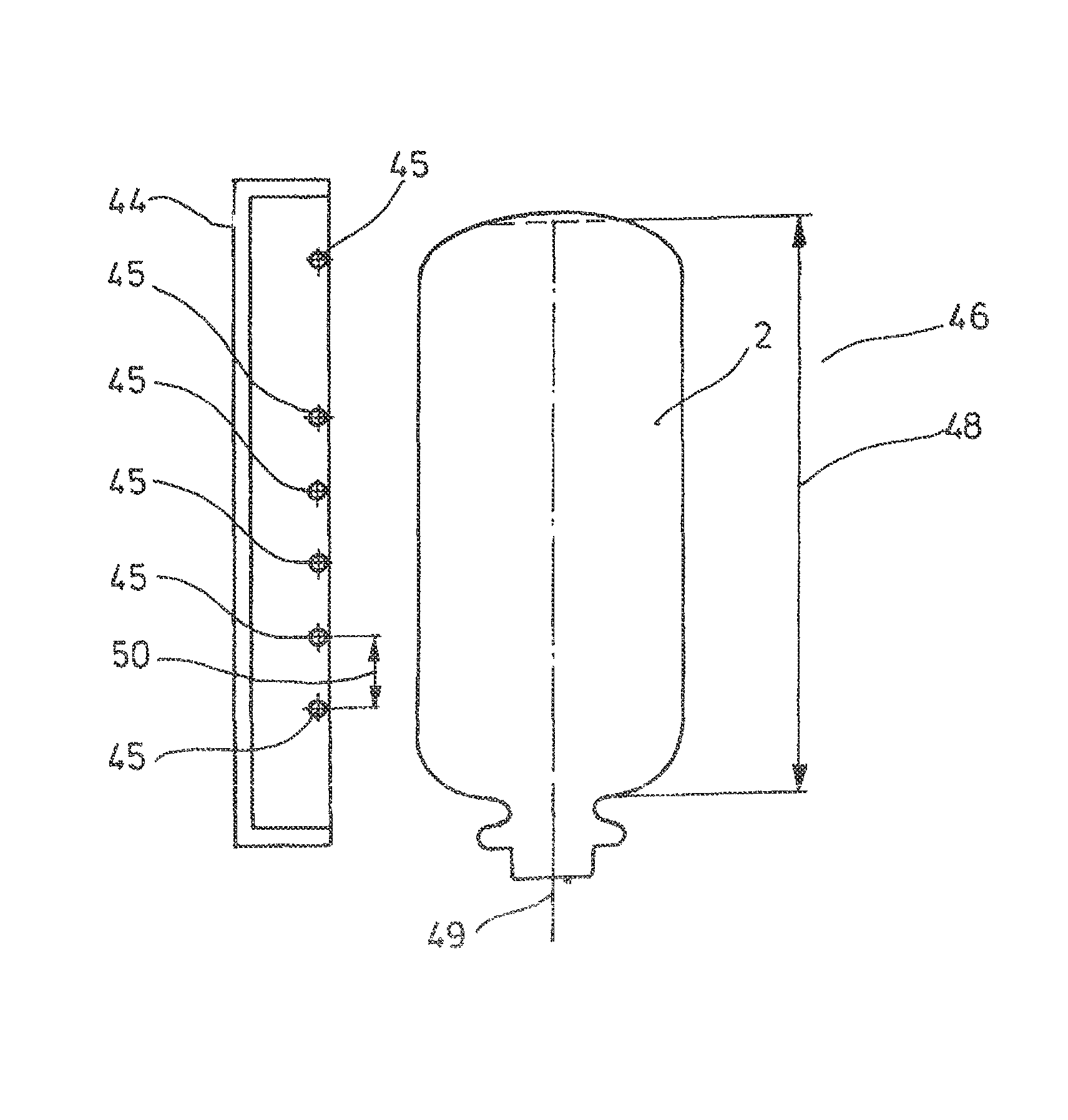
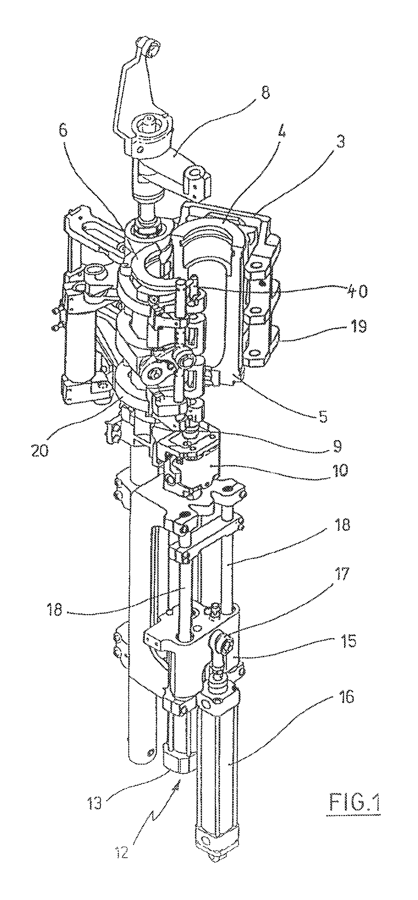
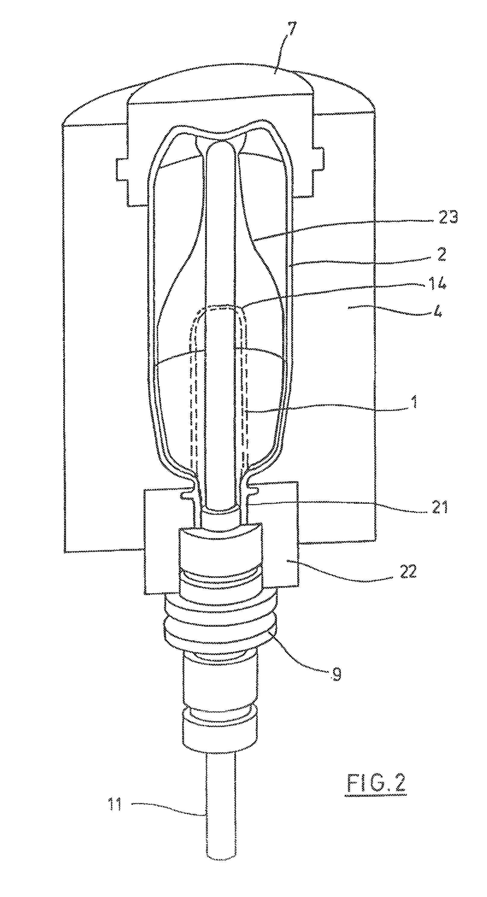
[0039]FIGS. 1 and 2 show the basic design of a device for molding preforms 1 into containers 2.

[0040]The device for molding the container 2 consists essentially of a blowing station 3, which is provided with a blow mold 4, into which a preform 1 can be inserted. The preform 1 can be an injection-molded part made of polyethylene terephthalate. To allow the preform 1 to be inserted into the blow mold 4 and to allow the finished container 2 to be removed, the blow mold 4 consists of mold halves 5, 6 and a base part 7, which can be positioned by a lifting device 8. The preform 1 can be held in place in the area of the blowing station 3 by a transport mandrel 9, which, together with the preform 1, passes through a large number of treatment stations within the device. However, it is also possible to insert the preform 1 directly into the blow mold 4, for example, with grippers or other handling devices.

[0041]To allow compressed air to be fed in, a connecting piston 10 is arranged below th...


PUM

PropertyMeasurementUnit
Temperatureaaaaaaaaaa
Thicknessaaaaaaaaaa
Pressureaaaaaaaaaa

Abstract

A method and an apparatus for blow-molding containers are disclosed. A parison made of a thermoplastic material is first subjected to a thermal treatment in the zone of a heating section along a conveying path. The parison is then shaped into the container within a blow mold under the effect of a blowing pressure. Once the container has been blow-molded, a wall thickness is measured on at least one vertical level of the container. A preset value for the wall thickness is fed to a controller as a desired value, and the measured wall thickness is fed thereto as an actual value. The controller presets the quantity of at least one parameter influencing the blowing process in accordance with a difference between the desired value and the actual value. More specifically, the controller presets the quantity of at least one parameter influencing the supply of blowing gas. The quantity of the parameter is preset on the basis of a blowing process simulation model implemented in the controller.

Description

[0001]The present application is a 371 of international application PCT / DE2009 / 001267 filed Sep. 7, 2009, which claims priority of DE 10 2008 057 999.8, filed Nov. 13, 2008, the priority of these applications is hereby claimed and these applications are incorporated herein by reference.BACKGROUND OF THE INVENTION[0002]The invention concerns a method for blow molding containers, in which a preform made of a thermoplastic material is subjected to thermal conditioning along a conveyance path in a heating line and then molded into a container in a blow mold by the action of blowing pressure; in which, after the container has been blow molded, a wall thickness is measured at at least one height level of the container; in which an automatic control system is supplied with a preassigned value for the wall thickness as the setpoint value and with the measured wall thickness as the actual value; and in which the automatic control system presets a value of at least one parameter that affects ...

Claims


Application Information

Patent Timeline
IPC IPC(8): B29C49/78
CPCB29C49/78B29C49/06B29C49/12B29C49/36B29C49/6445B29C49/783B29C2049/1257B29C2049/1271B29C2049/4889B29K2023/12B29K2067/00B29C49/1222B29C49/1229B29C49/42095B29C49/42402B29C2949/0715B29C49/6435B29C2049/7831B29C2049/7832B29C2049/7861B29C2049/78675B29C2049/78715B29C2049/7874B29C2049/78805B29C49/42398
Inventor HAESENDONCKX, FRANKBALKAU, KARL-HEINZGERNHUBER, MATTHIAS
Owner KHS GMBH
Why Eureka
Try Eureka