Transfer image forming method, transfer image forming apparatus, and intermediate transfer member to be used therein

a technology of transfer image and forming apparatus, which is applied in the direction of typewriters, duplicating/marking methods, printing, etc., can solve the problems of transfer failure, curling and cockling, and insufficient investigation, and achieve the effect of improving the transferability and detachability of an intermediate image and more elasticity

Inactive Publication Date: 2015-08-11
CANON KK
View PDF11 Cites 23 Cited by
  • Summary
  • Abstract
  • Description
  • Claims
  • Application Information

AI Technical Summary

Benefits of technology

[0010]The inventors of the present invention have made extensive studies on the problems of the related art. As a result, the inventors have found that an intermediate transfer member has only to be constructed as described below. The intermediate transfer member is constructed so that the intermediate transfer member has more elasticity, the temperatures of an intermediate image and the intermediate transfer member easily increase until the intermediate image is transferred, and the intermediate transfer member easily cools at the time of the transfer of the intermediate image. Therefore, an object of the present invention is to provide an intermediate transfer member with improved transferability and detachability of an intermediate image, a transfer image forming method involving using the member, and a transfer image forming apparatus including the member.
[0014]The transfer image forming method, the transfer image forming apparatus, and the intermediate transfer member to be used therein, which improve transferability and detachability of an ink image, can be provided.

Problems solved by technology

Bleeding, which means such a phenomenon that inks applied adjacently to each other are mixed with each other, and beading, which means such a phenomenon that an ink that has impacted earlier is attracted by an ink that has impacted later, are known as problems at the time of the formation of an image by an ink jet system.
In addition, there are problems such as curling and cockling due to excessive absorption of a liquid component in an ink by a recording medium.
However, Japanese Patent Application Laid-Open No. 2004-114675 has no description concerning a technology for improving the transferability or detachability of an ink image from the intermediate transfer member.
The transferability or the detachability is of concern particularly upon continuous printing at a high speed, and such problem has not been sufficiently investigated in the related art.
Accordingly, when an ink layer to be transferred is as thin as about 1 to 3 μm, the elastic layer cannot follow the irregularities of a paper surface at the time of the transfer and hence a transfer failure occurs.

Method used


Image

  • Transfer image forming method, transfer image forming apparatus, and intermediate transfer member to be used therein
  • Transfer image forming method, transfer image forming apparatus, and intermediate transfer member to be used therein
  • Transfer image forming method, transfer image forming apparatus, and intermediate transfer member to be used therein

Examples


example 1

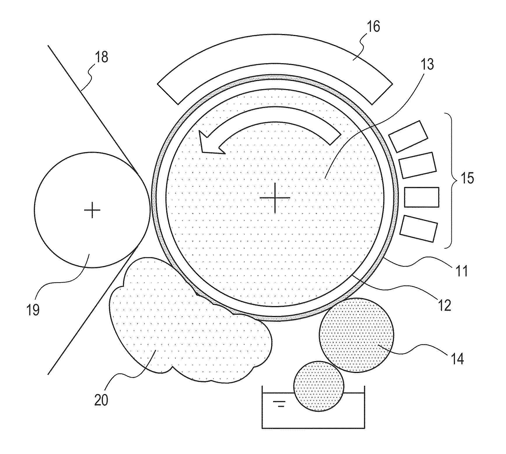
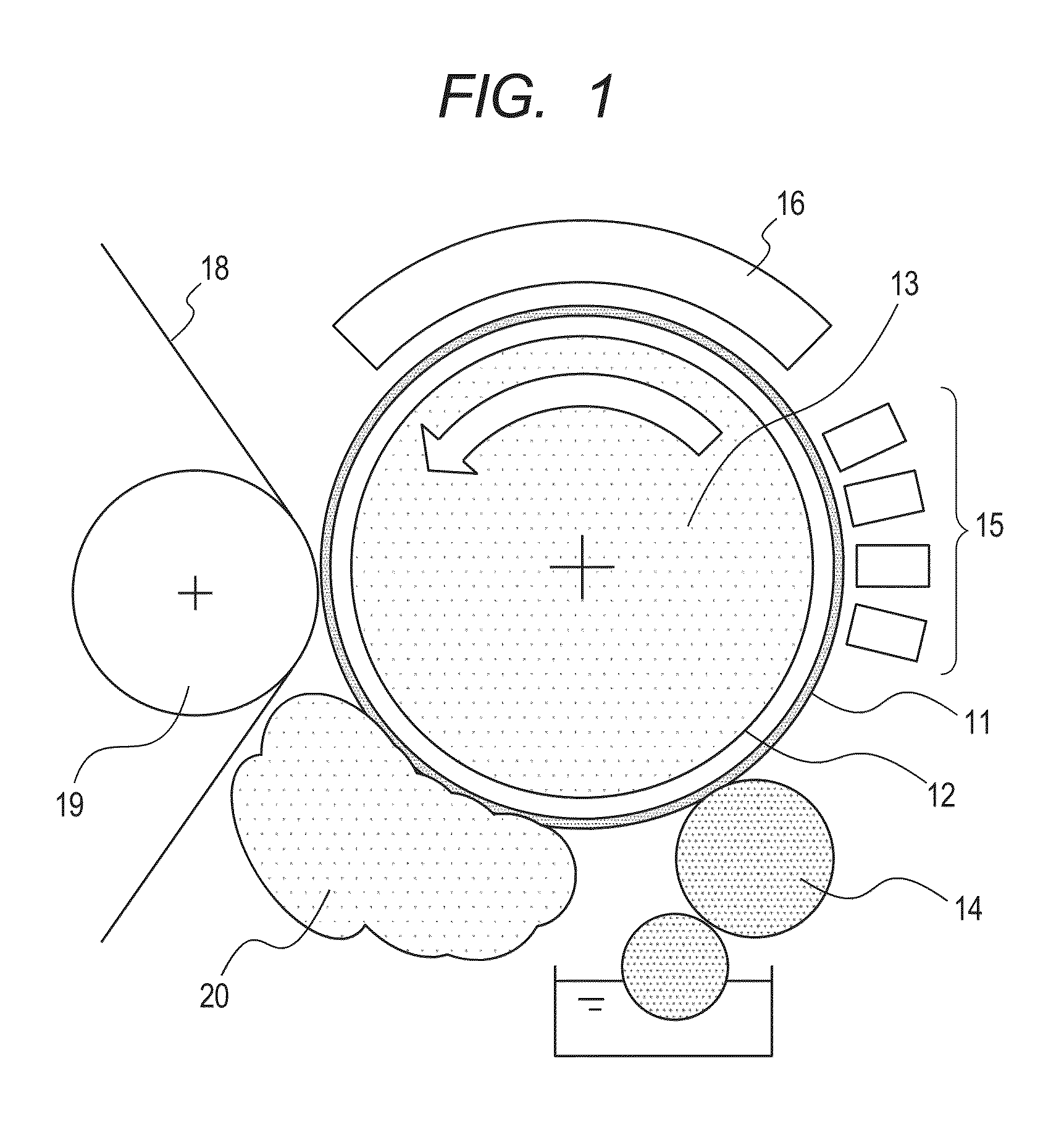
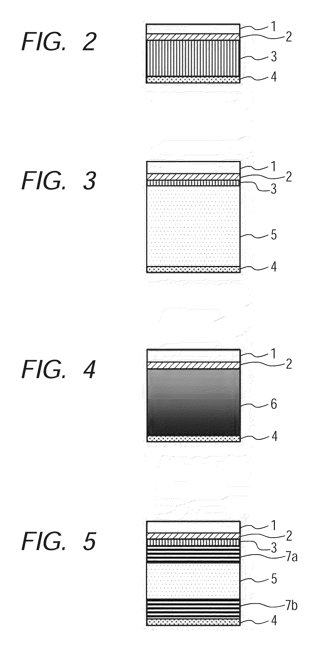
[0124]In this example, the transfer image forming apparatus illustrated in FIG. 1 was used. A member having the layer construction of FIG. 3 was used as the intermediate transfer member 11 of the transfer image forming apparatus. That is to say, in the intermediate transfer member 11, the surface layer (first layer), the metal layer, the heat insulating layer (second layer), the pressure relaxing layer, and the substrate 12 are placed in the stated order from the surface side of the intermediate transfer member 11. A cylindrical drum formed of an aluminum alloy was used as the substrate 12. Hereinafter, the construction of each layer on the substrate 12 is described.

[0125](i) Surface Layer (First Layer)

[0126]Used in this example was a surface layer obtained by coating a PET sheet having a thickness of 0.5 mm with a 0.2-mm thick layer of a silicone rubber having a rubber hardness of 40° (KE12 manufactured by Shin-Etsu Chemical Co., Ltd.); and then detaching the layer from the PET she...

example 2

[0137]The same apparatus as that of Example 1 was used except that the intermediate transfer member 11 was changed to the following member corresponding to that having the layer construction of FIG. 2.

[0138](i) Surface Layer (First Layer)

[0139]The same layer as that of Example 1 was used.

[0140](ii) Metal Layer

[0141]Gold having a thickness of 30 μm was used.

[0142](iii) Heat Insulating Layer (Second Layer)

[0143]Foamed polystyrene having a thickness of 0.5 mm (heat conductivity: 0.03 W / m·K) was used. Although no pressure relaxing layer is provided here, the heat insulating layer has elasticity because a foaming material is used in the layer. According to this construction, (heat conductivity) / (thickness) of the second layer is 60 (W / m2·K), which is a value smaller than (heat conductivity) / (thickness) of the first layer, i.e., 800 (W / m2·K).

example 3

[0144]The same apparatus as that of Example 1 was used except that the intermediate transfer member 11 was changed to the following member corresponding to that having the layer construction of FIG. 3.

[0145](i) Surface Layer (First Layer)

[0146]The same layer as that of Example 1 was used.

[0147](ii) Metal Layer

[0148]Gold having a thickness of 30 μm was used.

[0149](iii) Heat Insulating Layer (Second Layer)

[0150]Foamed polystyrene having a thickness of 0.1 mm (heat conductivity: 0.03 W / m·K) was used.

[0151](iv) Pressure Relaxing Layer (Third Layer)

[0152]An NBR having a thickness of 1 mm (heat conductivity: 0.2 W / m·K) was used.

[0153]According to this construction, (heat conductivity) / (thickness) of the second layer is 300 (W / m2·K), which is a value smaller than (heat conductivity) / (thickness) of the first layer, i.e., 800 (W / m2·K).


PUM

PropertyMeasurementUnit
surface temperatureaaaaaaaaaa
temperatureaaaaaaaaaa

Abstract

A transfer image forming apparatus includes ink applying unit for applying ink to an intermediate transfer member to form an intermediate image; a heating unit for irradiating the intermediate transfer member with at least infrared light to heat the intermediate image; and a transferring unit for pressing a recording medium against the intermediate transfer member having formed thereon the intermediate image to transfer the intermediate image onto the recording medium. The intermediate transfer member includes a substrate, and at least a second layer, a metal layer, and a first layer as a surface layer provided in the listed order on the substrate. The heat conductivity of the second layer is smaller than that of the first layer.

Description

BACKGROUND OF THE INVENTION[0001]1. Field of the Invention[0002]The present invention relates to a transfer image forming method, a transfer image forming apparatus, and an intermediate transfer member to be used therein.[0003]2. Description of the Related Art[0004]Bleeding, which means such a phenomenon that inks applied adjacently to each other are mixed with each other, and beading, which means such a phenomenon that an ink that has impacted earlier is attracted by an ink that has impacted later, are known as problems at the time of the formation of an image by an ink jet system. In addition, there are problems such as curling and cockling due to excessive absorption of a liquid component in an ink by a recording medium.[0005]A transfer ink jet printing method has been devised for solving the problems. The printing method includes the following steps:(1) an intermediate image forming step of applying an ink containing a coloring material component onto an intermediate transfer me...

Claims


Application Information

Patent Timeline
Patent Type & Authority Patents(United States)
IPC IPC(8): B41J2/01B41J2/005B41J1/00
CPCB41J1/00B41J2/0057B41M5/0256
Inventor KOITABASHI, NORIBUMITERAI, HARUHIKOOHNISHI, TORU
Owner CANON KK
Why Eureka
Try Eureka