
Control method for CVVL engine

a control method and engine technology, applied in the direction of machines/engines, electrical control, output power, etc., can solve the problems of self-ignition, knocking phenomenon, and increase the compression ratio, so as to prevent the deterioration of fuel efficiency and the knocking phenomenon, and effectively reduce the valid compression ratio

Active Publication Date: 2015-08-11
HYUNDAI MOTOR CO LTD +1
View PDF16 Cites 3 Cited by
  • Summary
  • Abstract
  • Description
  • Claims
  • Application Information

AI Technical Summary

Benefits of technology

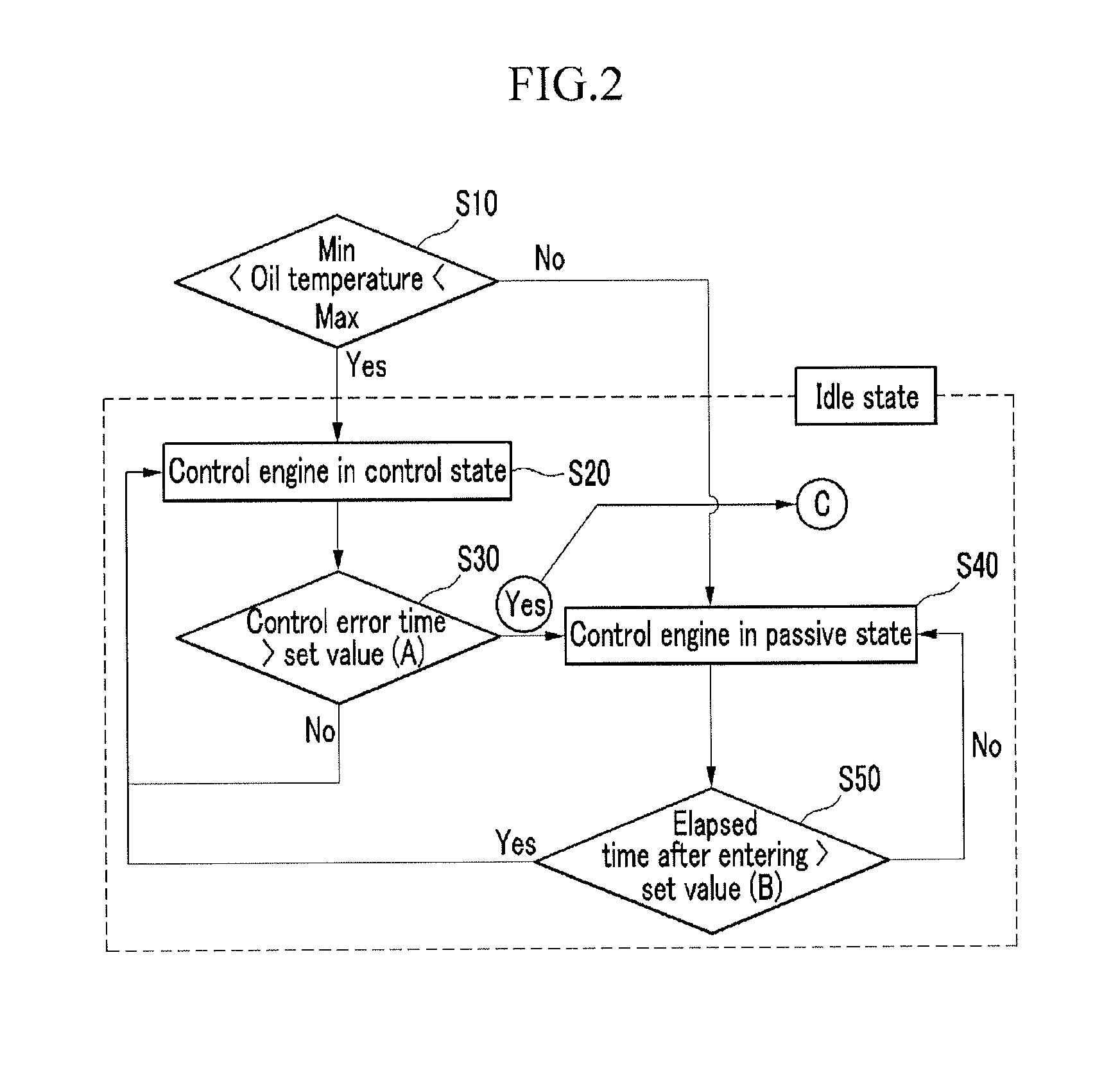
The present invention provides a control method for a continuous variable valve lift device that can prevent deterioration of fuel efficiency and a knocking phenomenon by effectively decreasing a valid compression ratio even in an idle state of an engine. The control method includes a control unit that determines when sufficient oil pressure is not formed in the idle state of the engine and performs a control while switching the engine to a passive state to prevent knocking. After a predetermined time has elapsed, the engine is controlled by switching it back to the control state to improve fuel efficiency.

Problems solved by technology

Meanwhile, when the engine tips in an idle state, a compression ratio is increased and self-ignition occurs due to a sudden increase of an air quantity, and as a result, a knocking phenomenon occurs.
In the related art, the knocking phenomenon was prevented by decreasing the valid compression ratio by designating one method between the two methods, but when the engine is in the idle state, advancing of the intake cam may be impossible due to insufficient oil pressure.
However, in the related art, since a countermeasure considering the case in which the cam advancing is impossible was not provided, appropriate action cannot be taken, and as a result, the knocking phenomenon occurred or the fuel efficiency deteriorated.

Method used


Image

  • Control method for CVVL engine
  • Control method for CVVL engine
  • Control method for CVVL engine

Examples


Embodiment Construction

[0036]Reference will now be made in detail to various embodiments of the present invention(s), examples of which are illustrated in the accompanying drawings and described below. While the invention(s) will be described in conjunction with exemplary embodiments, it will be understood that the present description is not intended to limit the invention(s) to those exemplary embodiments. On the contrary, the invention(s) is / are intended to cover not only the exemplary embodiments, but also various alternatives, modifications, equivalents and other embodiments, which may be included within the spirit and scope of the invention as defined by the appended claims.

[0037]Hereinafter, exemplary embodiments of the present invention will be described below in detail with reference to the accompanying drawings.

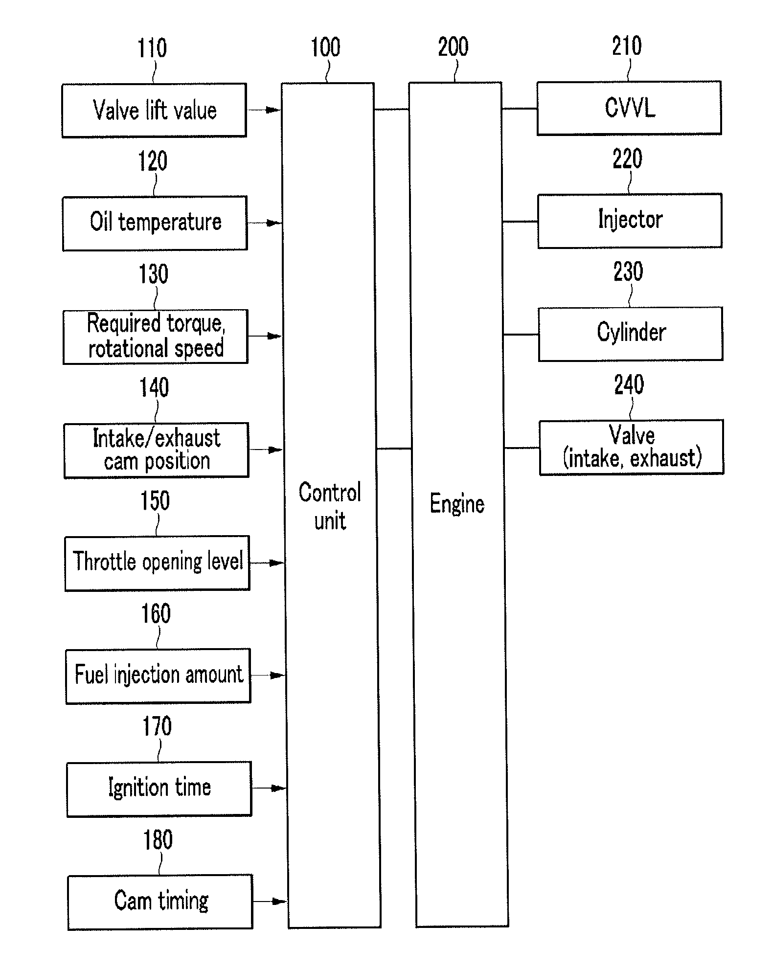
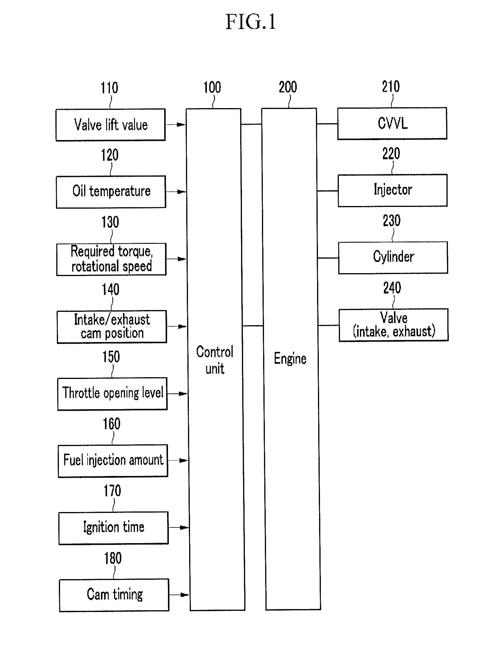
[0038]FIG. 1 is a schematic diagram of a control system of a continuous variable valve lift engine according to an exemplary embodiment of the present invention.

[0039]As illustrated in FIG...


PUM


Abstract

A continuous variable valve lift engine may include determining whether an engine is in an idle state and an oil temperature of an engine is within a predetermined range, controlling, the engine in a predetermined control state when the engine is in the idle state and the oil temperature is within the predetermined range, and measuring, an error occurrence time when an error occurs in controlling the engine in the control state, and controlling the engine while switching the engine to a predetermined passive state when the error occurrence time is more than a preset time.

Description

CROSS-REFERENCE TO RELATED APPLICATION[0001]The present application claims priority to Korean Patent Application No. 10-2012-0079404 filed on Jul. 20, 2012, the entire contents of which is incorporated herein for all purposes by this reference.BACKGROUND OF THE INVENTION[0002]1. Field of the Invention[0003]The present invention relates to a control method for a continuous variable valve lift (CVVL) engine. More particularly, the present invention relates to a control method for a CVVL engine for preventing a knocking phenomenon in an idle state of the engine.[0004]2. Description of Related Art[0005]An internal combustion engine combusts mixed gas in which fuel and air are mixed at a predetermined ratio through a set ignition mode to generate power by using explosion pressure.[0006]In this case, a cam shaft is driven by a timing belt connected with a crank shaft that converts linear motion of a cylinder by the explosion pressure into rotating motion to actuate an intake valve and an ...

Claims


Application Information

Patent Timeline
Patent Type & Authority Patents(United States)
IPC IPC(8): F02D41/00F01L13/00F02D13/02F02D41/08F02D41/22
CPCF02D41/00F02D13/02F01L13/0015F02D13/0207F02D15/00F02D41/08F02D41/22F02D2041/001F02D2200/023F01L2013/0068F01L2013/0073F01L2800/00F01L2800/04F01L2800/05Y02T10/12F01L13/00
Inventor RYU, IN SANGPARK, JONG BUM
Owner HYUNDAI MOTOR CO LTD
Learn More