Method for quasi-continuous dynamic motion correction in magnetic resonance measurements

a magnetic resonance and quasi-continuous technology, applied in the field of mr (= magnetic resonance) imaging and spatially resolved mr spectroscopy, can solve the problems of disturbance of the condition, no motion correction is possible, and the time progression of mr acquisition has to be adapted for motion correction, etc., to achieve simple but effective

Active Publication Date: 2015-08-11
UNIVERSITATSKLINIKUM FREIBURG
View PDF11 Cites 22 Cited by
  • Summary
  • Abstract
  • Description
  • Claims
  • Application Information

AI Technical Summary

Benefits of technology

[0026]According to the invention, this object is achieved in a surprisingly simple but effective manner in that the motion correction is applied during a signal weighting period, during a signal read-out period, or between and / or during the two stated periods, and that the adaptations for motion correction can be performed without interrupting or slowing the temporal progression of the MR acquisition.

Problems solved by technology

The timing of the MR acquisition with quasi-continuous motion correction must be complied with (no time demand for motion correction).One problem of many methods already described is that the time progression of the MR acquisition has to be adapted for motion correction.
If the required interruption in the signal progression of the sequence does not arise, or cannot be created, no motion correction is possible.
If the object moves, this condition might be disturbed.

Method used


Image

  • Method for quasi-continuous dynamic motion correction in magnetic resonance measurements
  • Method for quasi-continuous dynamic motion correction in magnetic resonance measurements
  • Method for quasi-continuous dynamic motion correction in magnetic resonance measurements

Examples


Embodiment Construction

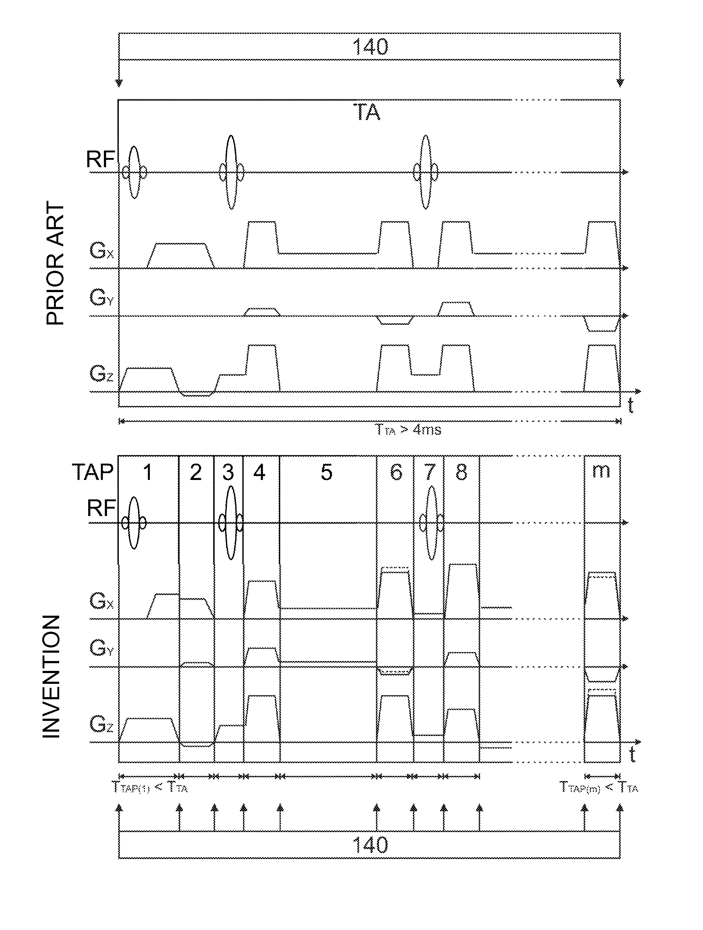
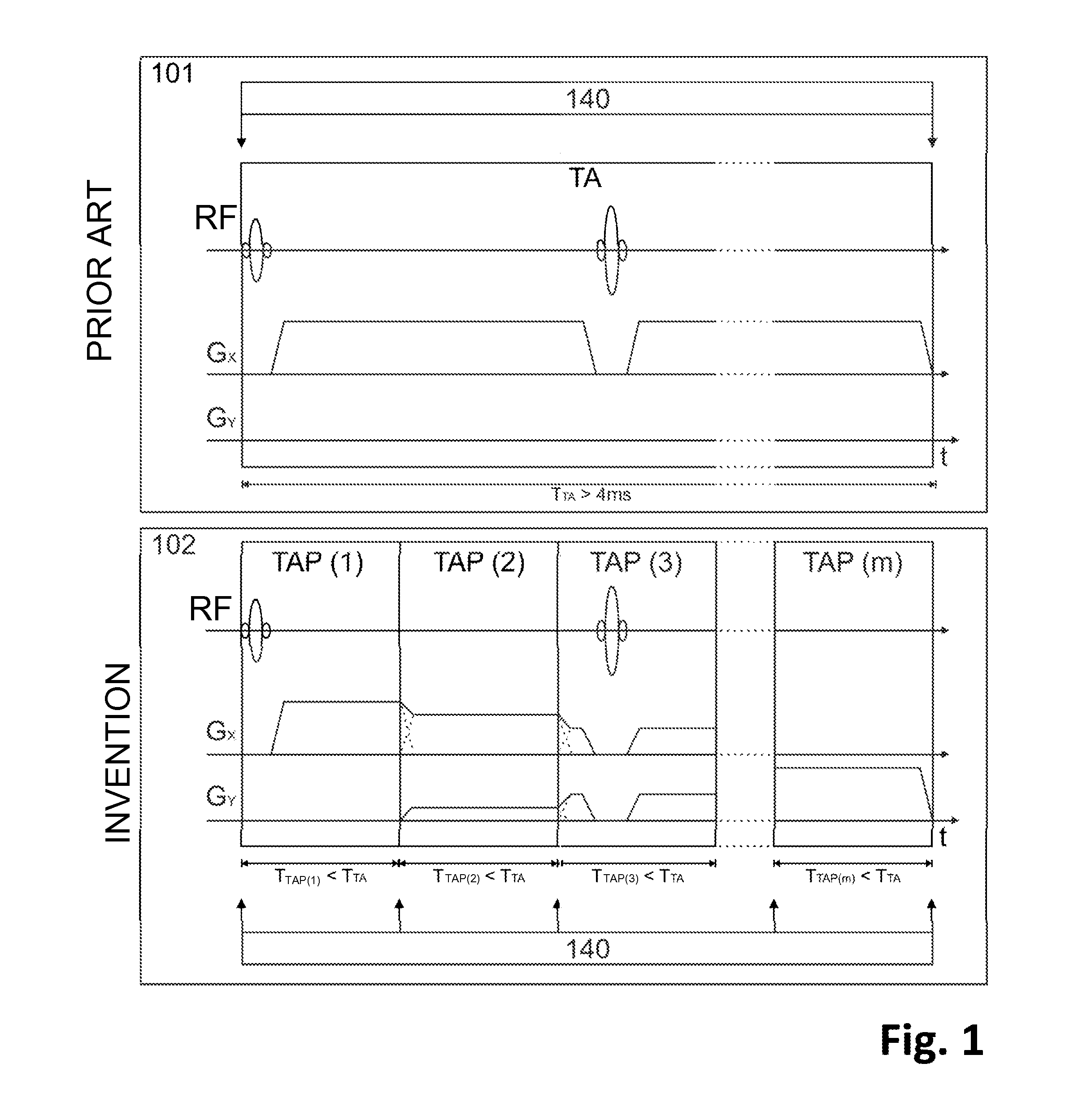
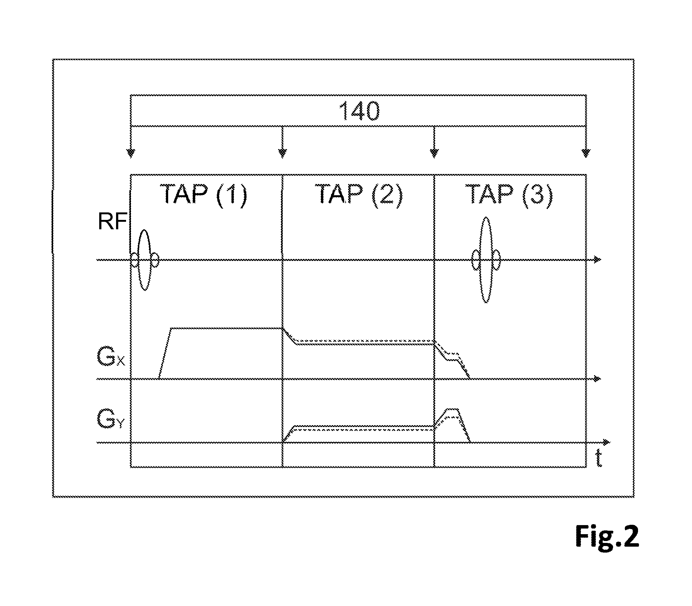
[0064]FIG. 1 shows a chart of the method for dynamic motion correction during a partial acquisition TA, wherein the partial acquisition is divided into shorter partial acquisition partitions TAP(1), TAP(2), TAP(3), . . . , TAP(m), wherein if long gradients are necessary they are divided into shorter partial gradients 101. The figures indicate the times for partial acquisition and for the partial acquisition periods with the symbols TTA, TTAP(1), TTAP(2), TTAP(3) and TTAP(m), respectively. For comparison, the corresponding partial acquisition without the use of the described method is shown in 102. A partial gradient is always switched off when the following gradient begins. An uninterrupted transition results from the rise and decay time of a gradient. The measurement system 140 determines position data with which motion correction is performed.

[0065]The partial acquisition shown is the section of an MR acquisition for DWI. DWI is frequently used in everyday clinical practice to rep...


PUM


Abstract

A method of MR imaging and spectroscopy to reduce artifacts occurring due to the motion of an object to be represented, wherein the object position is determined quasi-continuously during the runtime of the MR acquisition, which includes one or more partial acquisitions (TA), and wherein motion correction is performed, which comprises dynamic adaptation of the frequency and phase settings of the RF system of the tomograph and of the orientation and amplitudes of the gradients during the runtime of the MR acquisition according to the current object position. The motion correction is thereby applied during a signal weighting period, during a signal read-out period, or between and / or during the two stated periods and the adaptations for motion correction are performed without interrupting or slowing the temporal progression of the MR acquisition. In this way, artifacts due to motion of the object to be represented can be further reduced.

Description

[0001]This application claims Paris Convention priority of DE 10 2011 007 574.7 filed on Apr. 18, 2011.BACKGROUND OF THE INVENTION[0002]The invention relates to a method for MR (=magnetic resonance) imaging and spatially resolved MR spectroscopy using an MR tomograph to reduce artifacts occurring due to the motion of an object to be represented, wherein the object position is determined quasi-continuously during the runtime of the MR acquisition, which includes one or more partial acquisitions, and wherein motion correction is performed, which comprises dynamic adaptation of the frequency and phase settings of the RF (=radio frequency) system of the tomograph and of the orientation and amplitudes of the gradients during the runtime of the MR acquisition according to the current object position.[0003]Such a method is known from US 2009 / 0209846 A1 (=reference [1]).[0004]MR tomography, also known as magnetic resonance imaging (=MRI), MR imaging or magnetic resonance tomography (=MRT) i...

Claims


Application Information

Patent Timeline
Patent Type & Authority Patents(United States)
IPC IPC(8): G01R33/565G01R33/567
CPCG01R33/56509G01R33/5673
Inventor HERBST, MICHAELZAITSEV, MAXIMMACLAREN, JULIANWEIGEL, MATTHIAS
Owner UNIVERSITATSKLINIKUM FREIBURG
Why Eureka
Try Eureka