
Tidal stream generator

a generator and tidal stream technology, applied in the direction of motors, tidal stream/damless hydropower, buoyancy control, etc., can solve the problem that the generator does not operate at its maximum efficiency

Active Publication Date: 2015-08-25
LINELL RENEWABLES
View PDF71 Cites 21 Cited by
  • Summary
  • Abstract
  • Description
  • Claims
  • Application Information

AI Technical Summary

Benefits of technology

[0013]The power wheel may be rotationally mounted to the hub by rotary bearings. The shroud may be rotationally mounted to the hub or to the power wheel by rotary bearings. The power wheel and the shroud may each have controlled buoyancy, for example buoyant chambers which may be partially flooded to control the buoyancy, to minimise the vertical loads transferred through the rotary bearings.

Problems solved by technology

A further problem with prior art tidal stream generators is that they are optimised to work at a particular tidal flow rate.
At tidal flow rates higher or lower than the design tidal rate, the generator does not operate at its maximum efficiency.

Method used


Image

  • Tidal stream generator
  • Tidal stream generator
  • Tidal stream generator

Examples


Embodiment Construction

[0121]The operation of the buoyant submersible vertical axis tidal stream generator is as follows.

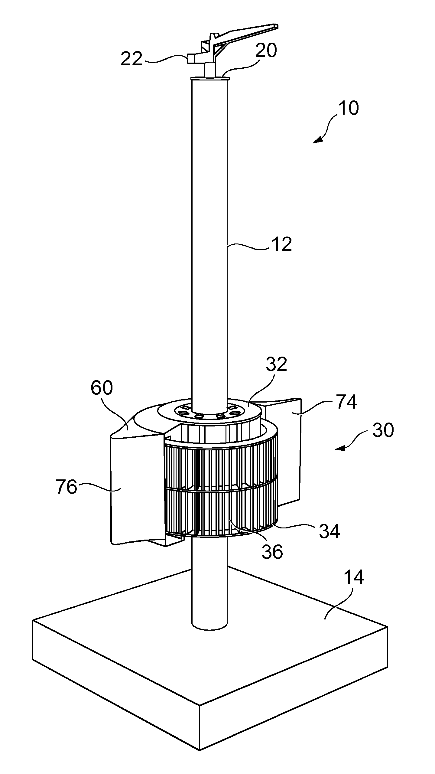
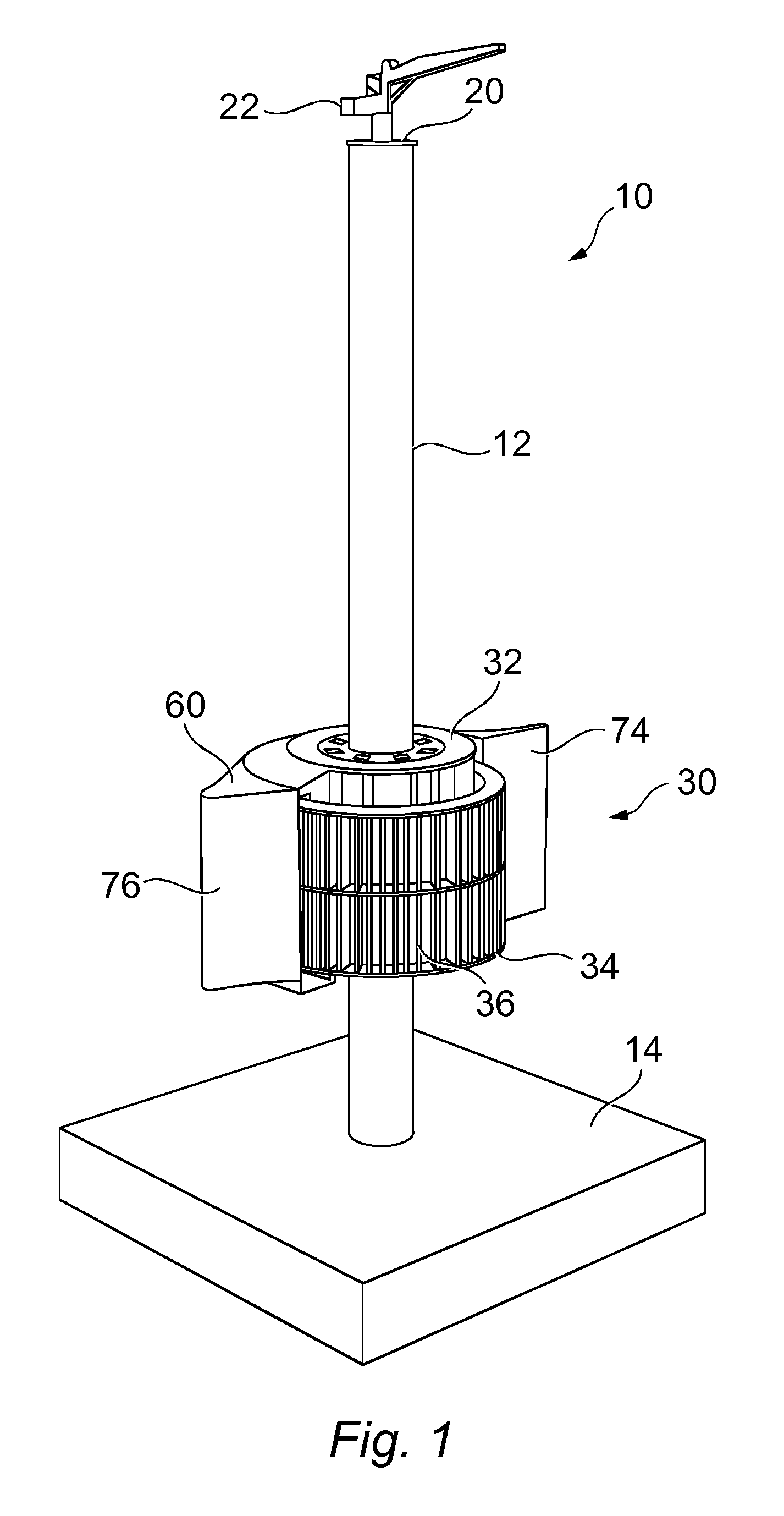
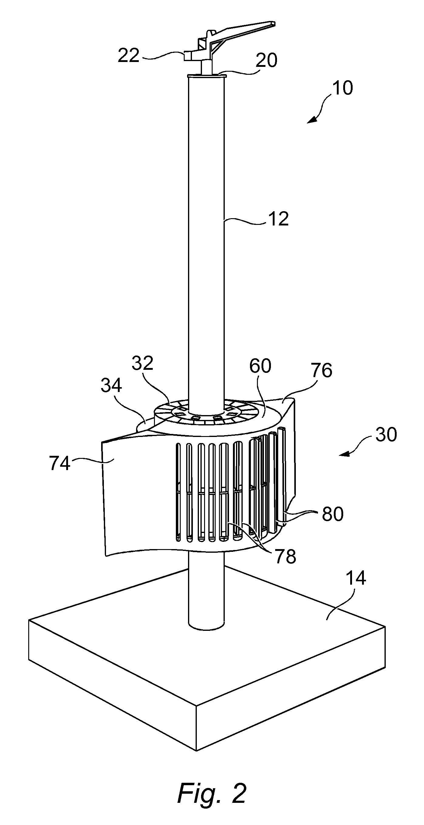
[0122]Referring to FIGS. 1 and 2 there is shown a generating apparatus 10 for converting kinetic energy from a substantially horizontal water flow to electrical energy, commonly referred to as a tidal stream generator. The apparatus includes a substantially vertical support structure 12 which is supported on the sea bed 14. In the illustrated example the support structure is a column fixed to the sea bed by any suitable means, for example the tripod structure 16 illustrated in FIG. 5. The tripod structure 16 may be anchored to the sea bed by three piles which engage in three pile sleeves 18. However any suitable structure may be used, for example a lattice structure or a plurality of columns or piles. Moreover any suitable means of supporting the structure on the sea bed may be used, for example a gravity structure, or direct support by directly driving the column or columns of the supp...


PUM


Abstract

A generating apparatus for generating electrical power from a horizontal water flow comprises a fixed hub on a support structure and a power wheel arranged for rotation about a vertical axis about the hub. The power wheel includes rotor vanes adapted to cause rotation of the power wheel when the power wheel is subject to a substantially horizontal water flow. One or more generators are provided on the hub to produce electrical power output from rotation of the power wheel relative to the hub. A shroud is rotationally mounted on the hub and arranged to cover at least some of the rotor vanes of the power wheel, so that the water flow is concentrated on the rotor vanes on one side only of the power wheel. A directional controller holds the shroud in a predetermined rotational position relative to the hub dependent on the direction of the water flow.

Description

FIELD OF THE INVENTION[0001]This invention relates to a generating apparatus for generating electrical power from a substantially horizontal water flow, for example tidal flow or river flow.BACKGROUND OF THE INVENTION[0002]Tidal stream generators generally use vanes or blades which rotate about a horizontal axis. GB 2 348 250 A describes a tidal stream generator which includes a support column mounted on a river or sea bed. The generator includes a turbine unit with blades which rotate about a horizontal axis. The turbine unit can be moved up and down the column by means of a cylindrical tank held inside the column. Water can be removed from the tank by displacing it with compressed air to lift the tank by buoyancy to a position in which the tank projects above the surface of the water. The turbine unit is fixed to the tank, so that when the tank is in its lifted position the turbine unit is at least partially above the surface of the water. The support column has a longitudinal slo...

Claims


Application Information

Patent Timeline
Patent Type & Authority Patents(United States)
IPC IPC(8): F03B13/10F03B13/12H02P9/04F03B13/26F03B17/06F03B15/00F03B13/00F03D9/00
CPCF03B13/10F03B13/264F03B15/00F03B17/063F05B2220/706F05B2240/13F05B2240/61F05B2240/97F05B2270/18Y02E10/28Y02E10/30Y02E10/20
Inventor ROSS, ROBERT
Owner LINELL RENEWABLES
Learn More