Microwave thermometry for microwave ablation systems

a microwave ablation and microwave technology, applied in the direction of optical radiation measurement, coupling device connection, instruments, etc., can solve the problem of limited measurement, and achieve the effect of reducing the duty cycle of the pwm microwave signal

Active Publication Date: 2015-09-01
COVIDIEN LP
View PDF230 Cites 11 Cited by
  • Summary
  • Abstract
  • Description
  • Claims
  • Application Information

AI Technical Summary

Benefits of technology

[0016]The microwave signal may be a pulse-width modulated (PWM) signal and the controller may cause the radiometer to measure noise temperature during each of the off times of the PWM signal. The controller may determine whether the measured noise temperature during the off periods of the PWM microwave signal is greater than a predetermined noise temperature value, and may shut off the microwave signal or reduce the duty cycle of the PWM microwave signal if it is determined that the measured noise temperature during the off periods of the PWM microwave signal is greater than a predetermined noise temperature value.
[0018]The microwave signal may be a pulse-width modulated (PWM) microwave signal and the method may include measuring the noise temperature during off periods of the PWM microwave signal. The method may include determining whether the measured noise temperature during the off periods of the PWM microwave signal is greater than a predetermined noise temperature value, and shutting off the microwave signal or reducing the duty cycle of the PWM microwave signal if it is determined that the measured noise temperature during the off periods of the PWM microwave signal is greater than a predetermined noise temperature value.

Problems solved by technology

These measurements, however, are limited to a small volume of tissue surrounding the measuring point of the thermoprobes.

Method used


Image

  • Microwave thermometry for microwave ablation systems
  • Microwave thermometry for microwave ablation systems
  • Microwave thermometry for microwave ablation systems

Examples


Embodiment Construction

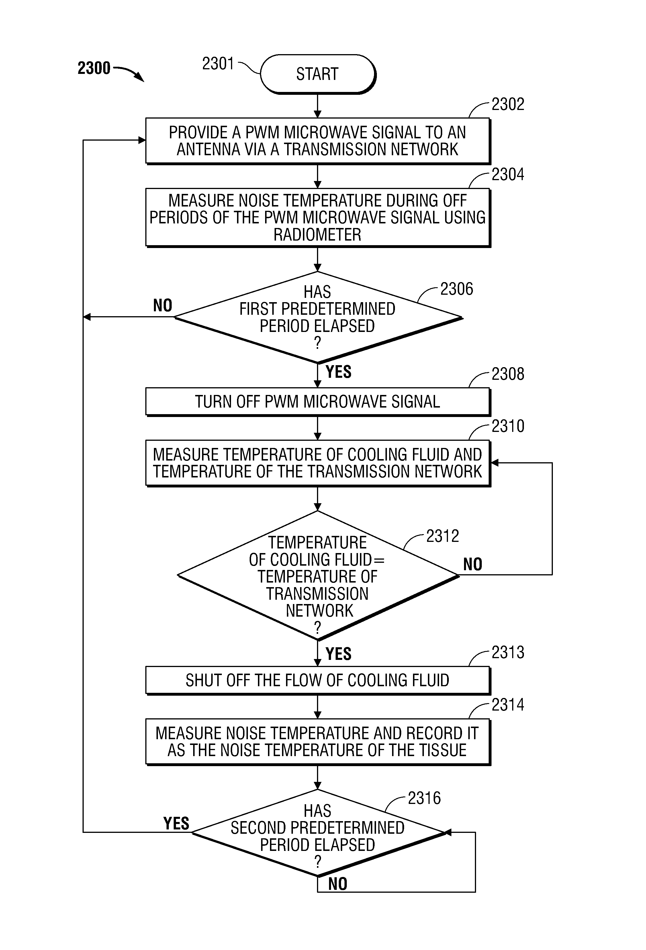
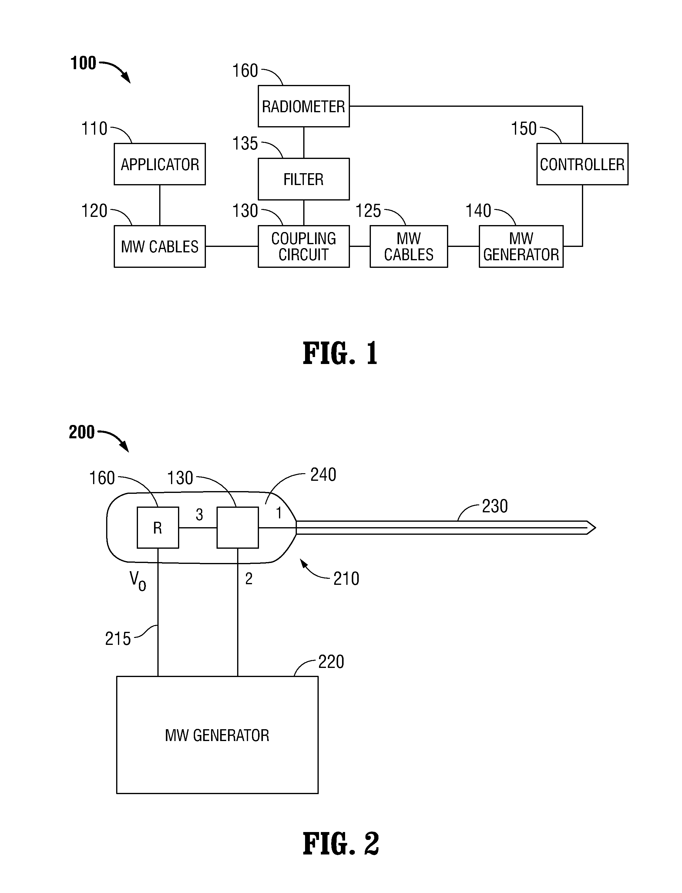
[0050]The present disclosure is generally directed to microwave ablation systems that incorporate a microwave thermometry network for monitoring the thermal characteristics of the microwave transmission network and the physiological environment surrounding a microwave applicator. Microwave radiometry is a technique for measuring electromagnetic energy considered as thermal radiation, and can be used to detect and measure microwave energy emanating from heat sources.

[0051]The microwave ablation systems according to the present disclosure combine an antenna transmitting energy to ablate tissue (at a set “ablation frequency”) with an antenna receiving thermal noise power emitted by heated tissue (at a set “radiometric frequency”) that can be translated into average temperature. If the radiometric frequency is high enough (e.g., 3-9 GHz), the temperature will be averaged over a small enough volume around the antenna (e.g., 1-3 mm), allowing the antenna to be used as a thermocouple.

[0052...


PUM

PropertyMeasurementUnit
temperatureaaaaaaaaaa
frequencyaaaaaaaaaa
frequencyaaaaaaaaaa

Abstract

A microwave ablation system incorporates a microwave thermometer that couples to a microwave transmission network connecting a microwave generator to a microwave applicator to measure noise temperature. The noise temperature is processed to separate out components the noise temperature including the noise temperature of the tissue being treated and the noise temperature of the microwave transmission network. The noise temperature may be measured by a radiometer while the microwave generator is generating the microwave signal or during a period when the microwave signal is turned off. The microwave ablation system may be configured as a modular system having one or more thermometry network modules that are connectable between a microwave applicator and a microwave generator. Alternatively, the modular system includes a microwave generator, a microwave applicator, and a microwave cable that incorporate a microwave thermometry network module.

Description

CROSS-REFERENCE TO RELATED APPLICATIONS[0001]This application claims the benefit of, and priority to, U.S. Provisional Patent Application No. 61 / 663,099 filed on Jun. 22, 2012, U.S. Provisional Patent Application No. 61 / 809,634 filed on Apr. 8, 2013, and U.S. Provisional Patent Application No. 61 / 837,633 filed on Jun. 20, 2013, the entire contents of each of which are incorporated by reference herein for all purposes.BACKGROUND[0002]1. Technical Field[0003]The present disclosure relates to microwave thermometry in microwave ablation systems.[0004]2. Discussion of Related Art[0005]Electromagnetic radiation can be used to heat and destroy tumor cells. Treatment may involve inserting ablation probes into tissues where cancerous tumors have been identified. Once the ablation probes are properly positioned, the ablation probes emit electromagnetic radiation into tissue surrounding the ablation probes.[0006]In the treatment of diseases such as cancer, certain types of tumor cells have bee...

Claims


Application Information

Patent Timeline
Patent Type & Authority Patents(United States)
IPC IPC(8): A61B18/18G01J5/46H01R13/66G01K11/00A61B18/00
CPCG01K11/006A61B18/1815G01J5/46H01R13/66A61B2018/00577A61B2018/00642A61B2018/00791A61B2018/00821A61B5/01A61B5/0507A61B2018/00666A61B2018/00702A61B2018/00988A61B2018/1823A61B2018/183G01J5/0837G01K7/02G01K13/00
Inventor BRANNAN, JOSEPH D.
Owner COVIDIEN LP
Why Eureka
Try Eureka