Combine harvester

a harvester and combine technology, applied in the field of combine harvesters, can solve the problems of affecting the supply of fertilizer, affecting the cleaning output of the harvesting operation on the slope, and changing the speed of the blower is the same effect across the entire, so as to reduce the installation space, facilitate the speed adjustment of the blower, and facilitate the effect of adaptation

Inactive Publication Date: 2015-09-08
CLAAS SELBSTFAHRENDE ERNTEMASCHINEN GMBH
View PDF33 Cites 6 Cited by
  • Summary
  • Abstract
  • Description
  • Claims
  • Application Information

AI Technical Summary

Benefits of technology

[0007]According to the present invention, the blowers can be controlled independently of one another. The independent control of the air volume flow output by the particular blower makes it possible to vary, in a flexible manner, the air volume flow supplied to the sieve system, in order to maintain the fluidized-bed phase across the entire width of the sieve system under varying harvesting and / or operating conditions. By way of the means, an air volume flow adapted to the harvesting conditions is generated, which can vary across the width of the sieve system. It is therefore possible, for example, to compensate an uneven formation of various separation states occurring on a slope, which is induced by the bulk phase which dominates on the downhill section of the sieve system due to gravity, and the flight phase which dominates on the uphill section of the sieve system. Likewise, the effects of an uneven distribution of crop across the width of the separating devices can be compensated.
[0020]In a preferred development, the means can be in the form of orifices having an adjustable opening width at inlet openings of the blower. To this end, sheet metal pieces which are displaceable in the radial direction can be disposed at the inlet openings of each blower to provide partial closing thereof. According to a simplified embodiment, two sheet metal pieces are provided, which are disposed on the blower housing in a manner that permits swivelling about an axis which is axially parallel to the blower. The two sheet metal pieces are moved toward one another to reduce the opening width of the inlet openings. In a further embodiment, an iris diaphragm is provided, by way of which the opening width can be changed. The iris diaphragm has the advantage that the air volume flow that can be drawn in can be controlled exactly. The orifices are provided with actuators which make it possible to control the orifices to vary the opening width and, therefore, the air volume flow that can be output by the particular blower. The control or regulation of the actuators, by way of which the orifices can be actuated, can take place in the manner described above depending on a crop and / or operating parameter.

Problems solved by technology

The consistency of the supply is greatly affected when the combine harvester is in a tilted position since gravity causes crop to accumulate on the sieve system.
A proven disadvantage of this blower system is that changing the blower speed has the same effect across the entire width of the sieve system.
The cleaning output during the harvesting operation on the slope is clearly impaired despite a constant flow across the width of the sieve system at low throughput rates, and therefore, due to the force of gravity, the bulk phase dominates in the crop on the downhill section of the sieve system, while the flight phase dominates on the uphill section of the sieve system.

Method used


Image

  • Combine harvester
  • Combine harvester
  • Combine harvester

Examples


Embodiment Construction

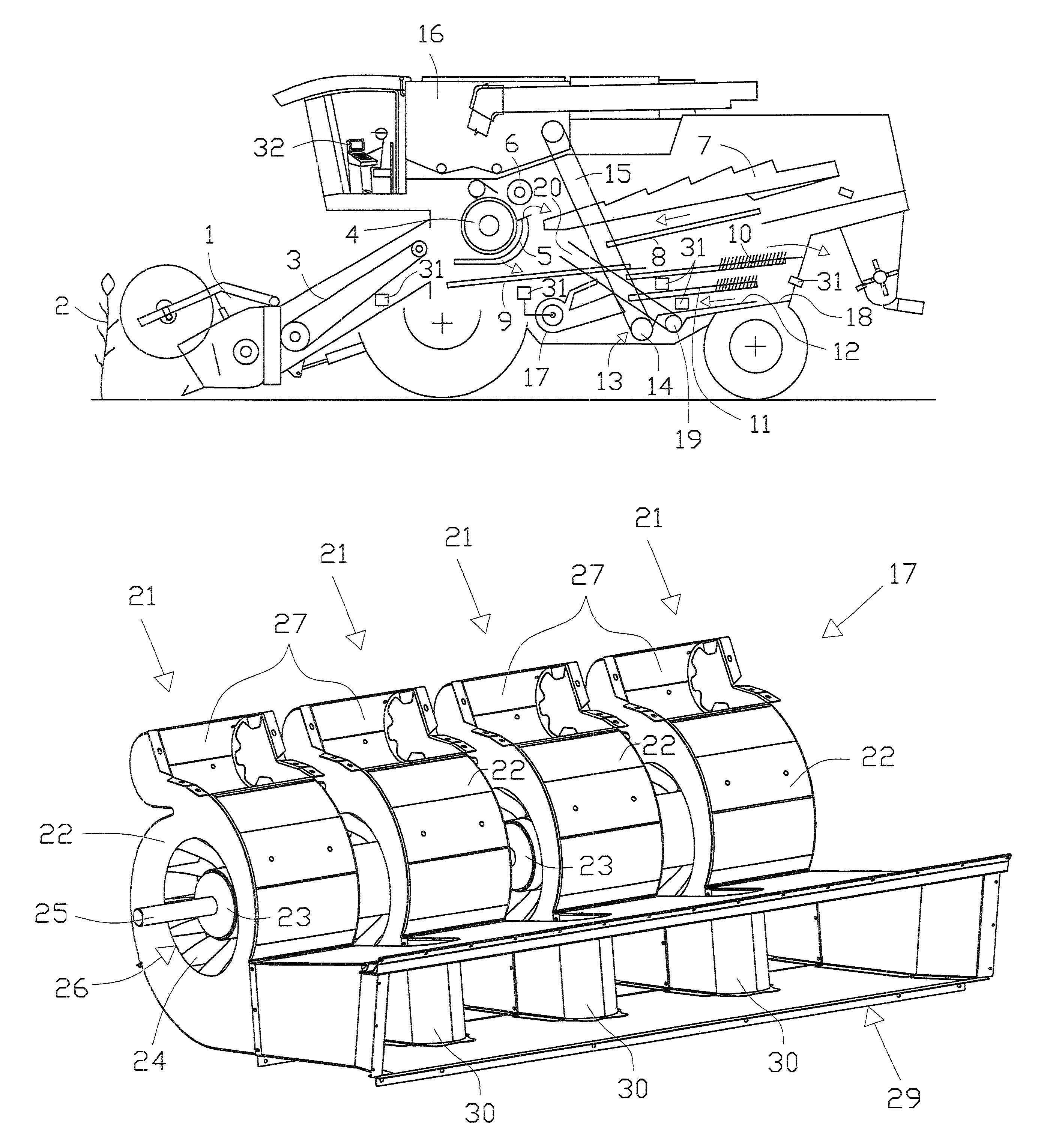
[0028]The combine harvester depicted schematically in FIG. 1 carries, on the front side thereof, a replaceable front attachment 1 such as a grain-cutting device for cutting and collecting crop 2. A feed rake 3 conveys the cut crop 2 to a threshing device oriented transversely to the direction of travel of the combine harvester, comprising a cylinder 4 and a concave 5. Grain threshed out of the crop 2 passes through the concave 5. An impeller 6 serves to further convey the threshed crop to a separating device 7 depicted here as a straw walker, which removes the remaining grain and small pieces of non-grain material from the flow of the threshed crop. Instead of the straw walker, an axial separator can be provided as the separating device 7, e.g. comprising one or two rotors extending in the longitudinal direction of the combine harvester, which are enclosed by separating grates.

[0029]Crop that has fallen through grates of the separating device 7 lands on a return pan 8 which extends ...


PUM


Abstract

A combine harvester has a cutting and conveyance device for crop, a threshing device for separating grain from the crop, a sieve system arranged in the longitudinal direction of the combine harvester, and a blower system comprising at least two blowers disposed upstream of the sieve system transversely to the longitudinal direction of the combine harvester and controlled independently of one another.

Description

CROSS-REFERENCE TO RELATED APPLICATION[0001]The invention described and claimed hereinbelow is also described in German Patent Application DE 10 2011 000 130.1 filed on Jan. 14, 2011. This German Patent Application, whose subject matter is incorporated here by reference, provides the basis for a claim of priority of invention under 35 U.S.C. 119(a)-(d).BACKGROUND OF THE INVENTION[0002]The present invention relates to a combine harvester. More particularly, it relates to a combine harvester having a cutting and conveyance device for crop, a threshing device for separating grain from the crop, a sieve system, and a blower system.[0003]DE 39 06 186 A1 makes known a combine harvester of the initially stated type, which comprises a cutting and conveyance device for crop, a threshing unit for separating the grain from the crop, and a sieve system extending in the longitudinal direction of the combine harvester. A blower system is disposed upstream of the sieve system, transversely to the ...

Claims


Application Information

Patent Timeline
Patent Type & Authority Patents(United States)
IPC IPC(8): A01F12/44A01D75/28
CPCA01F12/444A01D75/282
Inventor SCHULZ, WALDEMAR
Owner CLAAS SELBSTFAHRENDE ERNTEMASCHINEN GMBH
Why Eureka
Try Eureka