High pressure discharge lamp with auxiliary lamp

a technology of auxiliary lamps and discharge lamps, which is applied in the direction of gas discharge lamps, basic electric elements, light sources, etc., can solve the problems of low possibility of problems as described above, and achieve the effect of reducing the capacity of the power feeding device and lowering the applied voltag

Inactive Publication Date: 2015-09-08
PHOENIX ELECTRIC CO
View PDF2 Cites 0 Cited by
  • Summary
  • Abstract
  • Description
  • Claims
  • Application Information

AI Technical Summary

Benefits of technology

[0021]The large amount of ultraviolet rays UV is guided efficiently into the sealing portion 28a by arranging the large space 40a of the auxiliary lamp 14 so as to face the sealing portion 28a of the high pressure discharge lamp 12. The guided ultraviolet rays UV enter into the light-emitting part 26 and irradiate the main electrodes 20a, 20b arranged inside the light-emitting part 26. Consequently, electrons are emitted easily from the main electrodes 20a, 20b (photoelectric effect). And when the luminescent material M1 being enclosed inside the light-emitting part 26 is irradiated with the ultraviolet rays UV, the luminescent material M1 ionizes and a “discharging route” for generating the electric discharge between the main electrodes 20a, 20b is formed. Consequently, the high pressure discharge lamp 12 can be lighted instantaneously at cold start and at hot start using low applied voltage (for example, 1.2 kV).
[0022]In addition, when the arrangement angle θ2 of the reed-shaped metal foil 30a buried in the sealing portion 28a is set so as not to arrange the auxiliary lamp 14 in the face of the metal foil 30a, the ultraviolet rays UV are difficult to hit and be blocked by the metal foil 30a. The ultraviolet rays UV from the auxiliary lamp 14 are guided into the sealing portion 28a and proceed into the light-emitting part 26 after being reflected within the sealing portion 28a several times. Consequently, the ultraviolet rays UV from the auxiliary lamp 14 are affected to the main electrodes 20a, 20b effectively. The high pressure discharge lamp 12 can be lighted surely at cold start and at hot start using low applied voltage.
[0025]According to this embodiment, the amount of the ultraviolet rays UV guided into the sealing portion 28a can be increased. Consequently, the pressure discharge lamp 12 can be lighted with lower applied voltage surely.
[0027]According to this embodiment, the feeder wire 48 can be used as the outer electrode 38. Then, the number of components of the high pressure discharge lamp with auxiliary lamp 10 can be reduced.
[0029]According to this embodiment, overall radiating surface area of the high pressure discharge lamp with auxiliary lamp 10 can be increased because a part of the heat generated in the sealing portion 28a of the high pressure discharge limp 12 while lighting is conducted easily, to the auxiliary lamp 14. Then, the possibility for damage of the sealing portion 28a by the heat can be reduced, and it gives the high pressure discharge lamp 12 a longer life.

Problems solved by technology

But the lower the required lighting-up voltage is, the lower the possibility of the problems as described above is.

Method used


Image

  • High pressure discharge lamp with auxiliary lamp
  • High pressure discharge lamp with auxiliary lamp
  • High pressure discharge lamp with auxiliary lamp

Examples


Embodiment Construction

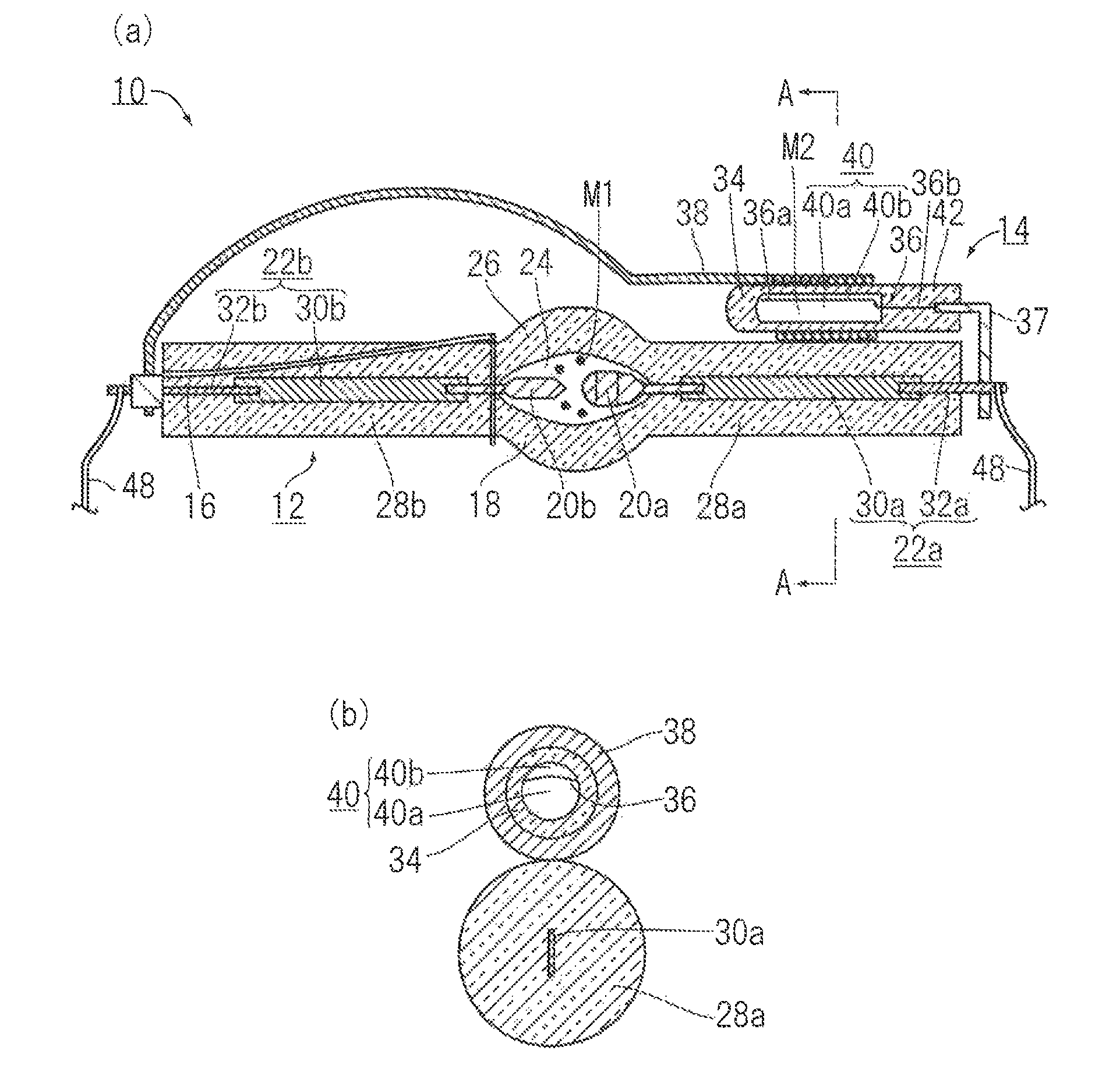
[0041]Embodiments of the high pressure discharge lamp with auxiliary lamp 10 in the present invention are explained by using figures as below. As shown in FIG. 1, a high pressure discharge lamp with auxiliary lamp 10 of this embodiment comprises: a high pressure discharge lamp 12; an auxiliary lamp 14; and a trigger wire 16.

[0042]The high pressure discharge lamp 12 has an arc tube 18, a pair of main electrodes 20a, 20b, and a pair of feeders 22a, 22b.

[0043]The arc tube 18 is made of quartz glass and has a light-emitting part 26 including an inner space 24 enclosing luminescent material M1 such as mercury or the like, and a pair of sealing portions 28a, 28b protruding from both sides of the light-emitting part 26 for sealing the inner space 24 of the light-emitting part 26. In addition, in this embodiment, the high pressure discharge lamp 12 has two sealing portions 28a, 28b. The high pressure discharge lamp having one sealing portion, as pointed out above, may be used.

[0044]The mai...


PUM


Abstract

A high pressure discharge lamp with auxiliary lamp comprises: a high pressure discharge lamp having an arc tube and at least one sealing portion, a pair of main electrodes, and a pair of feeders supplying power to the main electrodes; an auxiliary lamp having an airtight case, an inner electrode, and an outer electrode, wherein the inner electrode is arranged at a position so as to part the inner space to large and small spaces, the outer electrode is arranged at a position so as to face the large space, the auxiliary lamp as arranged as the large space faces the sealing portion.

Description

BACKGROUND OF THE INVENTION[0001]1. Field of the Invention[0002]The present invention relates to a high pressure discharge lamp having an auxiliary lamp that emits ultraviolet rays for decreasing required voltage value for lighting-up. The auxiliary lamp enhances lighting-up performance of the discharge lamp.[0003]2. Description of Related Art[0004]High pressure discharge lamps are mainly used as light sources for optical devices, for example liquid-crystal projectors, exposure devices or the like. The high pressure discharge lamp comprises: an arc tube having a space where luminescent materials such as mercury, halide, products from halogen cycle, or the like are enclosed; and a pair of main electrodes placed oppositely each other inside the arc tube. An electrical discharge by an insulation breakdown between the main electrodes that high voltage for lighting-up is applied excites the luminescent materials. The excited luminescent materials emit light.[0005]Recently, for reducing t...

Claims


Application Information

Patent Timeline
Patent Type & Authority Patents(United States)
IPC IPC(8): H05B37/00H01J61/54
CPCH01J61/54H01J61/547
Inventor IKEDA, TOMIHIKOTAKAHASHI, HIROSHIUSHIJIMA, SHINICHIGOUDA, TETSUYASHIMADA, KEI
Owner PHOENIX ELECTRIC CO
Why Eureka
Try Eureka