Methods, systems and devices for non-invasive ventilation including a non-sealing ventilation interface with an entrainment port and/or pressure feature
What is Al technical title?
Al technical title is built by PatSnap Al team. It summarizes the technical point description of the patent document.
a non-invasive ventilation and interface technology, applied in the field of ventilation therapy, can solve the problems of not being able to mechanically help, consuming a significant amount of oxygen, and burdening the patient,
Active Publication Date: 2015-09-15
BREATHE TECHNOLOGIES INC
View PDF1126 Cites 41 Cited by
Summary
Abstract
Description
Claims
Application Information
AI Technical Summary
This helps you quickly interpret patents by identifying the three key elements:
Problems solved by technology
Method used
Benefits of technology
[0014]Embodiments of the present invention may include a method of delivering a therapeutic level of gas to a patient wherein the amount of gas increases the pressure in the oropharyngeal airway to a pressure level able to reduce obstructive sleep apnea airway obstructions, the method including: attaching a nasal interface to a patient wherein the interface does not impede the patient from breathing ambient air directly through the interface; placing a jet nozzle in the nasal interface at the proximal end of the interface lateral to the nose, and placing an entrainment port in the nasal interface between the jet nozzle and the distal end of the nasal interface; attaching a ventilator to a gas delivery circuit and the gas delivery circuit to the jet nozzle and delivering gas from the ventilator to the nasal interface; delivering the gas from the nozzle into the nasal interface with a velocity that creates a negative pressure inside the interface at the location of the aperture, at a distance from the interface distal end; and the interface to create a positive pressure between the negative pressure area in the nasal interface and the interface distal end, wherein substantially all of the patient's exhaled gas flows through the ambient air entrainment aperture and virtually none flows through the gas delivery circuit, and wherein the therapeutic level of gas requires (a) gas from the ventilator and (b) ambient air entrained through the aperture by the velocity in the nasal interface created by the ventilation gas delivery.
Problems solved by technology
There is a need for a minimally obtrusive nasal mask and ventilation system that delivers mechanical ventilatory support or positive airway pressure, and which unencumbers the patient.
For example, some nasal mask oxygen therapy systems have been developed for the purpose of delivering mixtures of air and oxygen by entraining air into the mask, however these are not considered ventilation therapy or respiratory support, because they do not mechanically help in the work of breathing.
These systems are inefficient in that they consume a significant quantity of oxygen, rendering them non-mobile systems and encumbering the patient.
While helpful in supporting the work of breathing, the patient interfaces used for MV are obtrusive and / or invasive to the user, and MV does not facilitate mobility or activities of daily living, therefore encumbers that patient and is a drawback to many potential users.
However, the patient cannot use their upper airway because the interface makes an external seal against the nose and / or mouth, and in addition the system is not mobile, the combination of which does not enable activities of daily living.
Method used
Image
Click on the blue label to locate the original text in one second.
Reading with bidirectional positioning of images and text.
Examples
Embodiment Construction
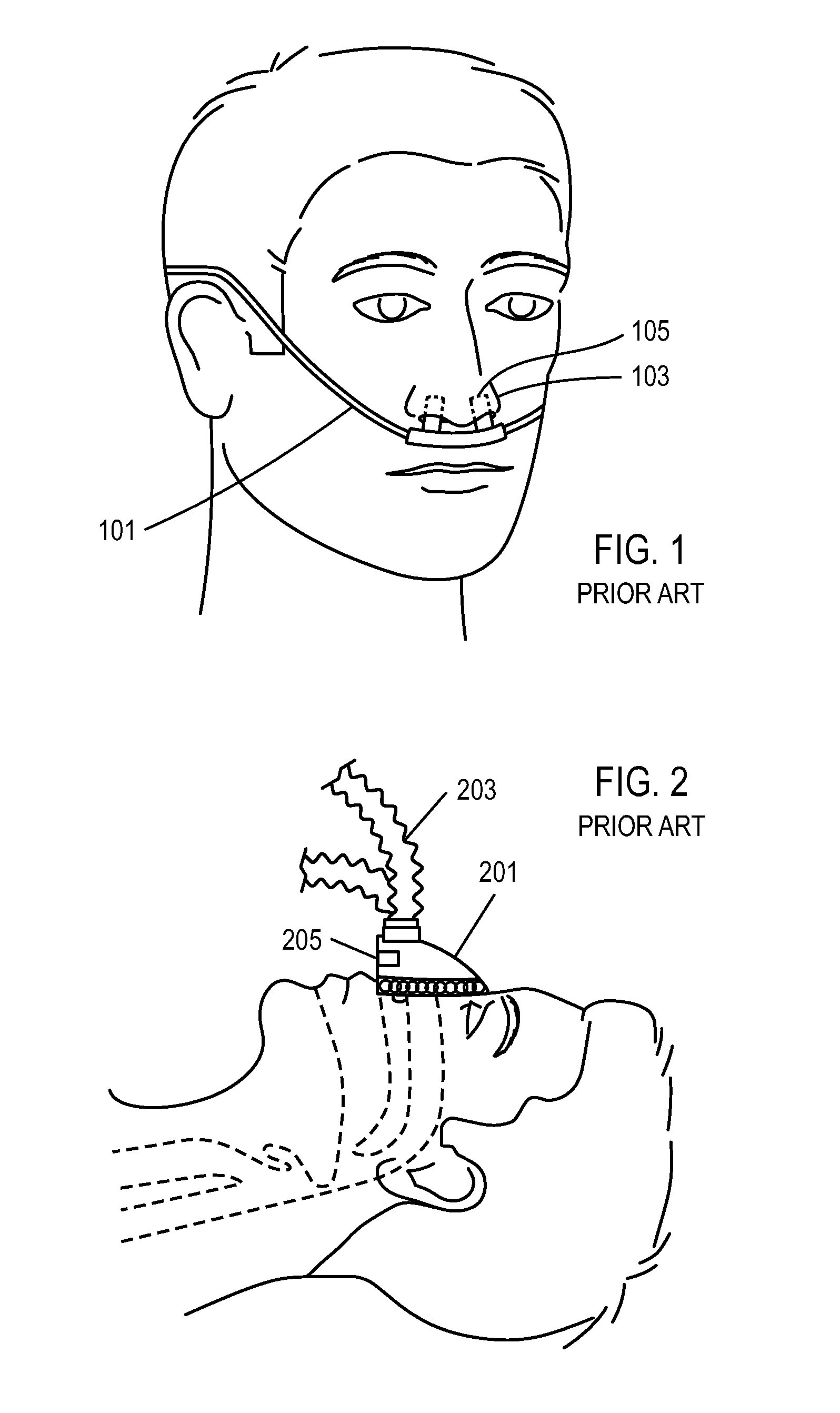
[0088]FIG. 1 shows a prior art conventional oxygen delivery cannula 101 for administering oxygen therapy. Extensions 105 on the cannula 101 are configured to enter nares 103. A proximal end (not shown) of the cannula 101 is connected to an oxygen delivery device that delivers continuous flow oxygen at 1-6 LPM to the user's nose, or delivers a bolus of oxygen upon detection of an inspiratory effort. The system of FIG. 1 does not mechanically support the work of breathing of the patient, and is not believed to be effective in preventing moderate to severe forms of OSA. The cannula of FIG. 1 is also used with another oxygen delivery therapy, high flow oxygen therapy (HFOT), in which more than 15 LPM of humidified oxygen is delivered at a continuous flow rate to the user's nose. Due to the high flow required for HFOT, the system is non-portable and the oxygen must be humidified.
[0089]FIG. 2 shows a prior art respiratory support therapy for non-invasive ventilation (NIV), using a nose ma...
PUM
Abstract
Systems and methods may include a gas source, a gas delivery circuit, and a nasal interface allowing breathing ambient air through the nasal interface. A gas flow path through the nasal interface may have a distal gas flow path opening. A nozzle may be associated with a proximal end of the nasal interface a distance from the distal end gas flow path opening. At least a portion of an entrainment port may be between the nozzle and the distal end gas flow opening. The nozzle may deliver gas into the nasal interface to create a negative pressure area in the gas flow path at the entrainment port. The nasal interface and the nozzle may create a positive pressure area between the entrainment port and the distal end gas flow path opening. Gas from the gas delivery source and air entrained through the entrainment port may increase airway pressure or lung pressure or provide ventilatory support.
Description
CROSS-REFERENCE TO RELATED APPLICATIONS[0001]This application claims priority to U.S. Provisional Patent Application No. 61 / 239,728, filed Sep. 3, 2009, U.S. Provisional Patent Application No. 61 / 255,760, filed Oct. 28, 2009, U.S. Provisional Patent Application No. 61 / 294,363, filed Jan. 12, 2010, and U.S. Provisional Patent Application No. 61 / 306,370, filed Feb. 19, 2010; the contents of which are incorporated by reference herein in their entireties. This application also claims priority to U.S. Non-Provisional patent application Ser. No. 12 / 753,846, filed Apr. 2, 2010, PCT Patent Application No. PCT / US2010 / 029871, filed Apr. 2, 2010, U.S. Non-Provisional patent application Ser. No. 12 / 753,851, filed Apr. 2, 2010, PCT / US2010 / 029873, filed Apr. 2, 2010, U.S. Non-Provisional patent application Ser. No. 12 / 753,853, filed Apr. 2, 2010, U.S. Non-Provisional patent application Ser. No. 12 / 753,854, filed Apr. 2, 2010, PCT Application No. PCT / US2010 / 029874, filed Apr. 2, 2010, U.S. Non-Pro...
Claims
Application Information
Patent Timeline
Application Date:The date an application was filed.
Publication Date:The date a patent or application was officially published.
First Publication Date:The earliest publication date of a patent with the same application number.
Issue Date:Publication date of the patent grant document.
PCT Entry Date:The Entry date of PCT National Phase.
Estimated Expiry Date:The statutory expiry date of a patent right according to the Patent Law, and it is the longest term of protection that the patent right can achieve without the termination of the patent right due to other reasons(Term extension factor has been taken into account ).
Invalid Date:Actual expiry date is based on effective date or publication date of legal transaction data of invalid patent.