CO2 fracturing system and method of use

a fracturing system and fracturing method technology, applied in the field of co sub > 2 /sub> fracturing system and method of use, can solve the problems of limiting commercial applications, limiting both proppant and cosub>2 /sub>storage capacity, and requiring an undetected long elapsed time for pressurized blenders

Inactive Publication Date: 2015-09-15
BAKER HUGHES OILFIELD OPERATIONS LLC
View PDF18 Cites 12 Cited by
  • Summary
  • Abstract
  • Description
  • Claims
  • Application Information

AI Technical Summary

Problems solved by technology

In addition, hydrocarbon production can be improved through reduced damage to the formation and proppant pack, yet several factors limit commercial application.
Current CO2 fracturing processes utilize pressurized proppant blending and storage of the amount of proppant required to complete a single fracturing stage under pressure to support blending, which limits both proppant and CO2 storage capacities.
The limited volume capacity of the proppant storage vessel system provides for limited amounts of proppant to be blended with the CO2 fracturing fluid.
In addition, these known pressurized blenders require an undesirably long elapsed time to reload them with proppant for the next fracture stage.
In some instances, some pressurized blender operations require the blender unit be moved off-site to another location for the purpose of reloading with proppant, also requiring an undesirably long time and potentially adding to the truck traffic associated with fracturing operations.
In many instances, the limited capacity requires specialized logistics and on-pad (or off-pad) proppant handling equipment to be used in conjunction with the proppant storage vessel based pressurized blenders.
As a result of the limited capacity of the proppant under pressure, injection rates and the volume of an output flow of CO2 / proppant slurry are limited since blender operation has to be periodically stopped to allow for refilling of proppant storage and / or supplying of CO2.
This stoppage in operation results in lost man-hours, or a larger number of blenders on the wellpad, either of which increases costs.

Method used


Image

  • CO<sub>2 </sub>fracturing system and method of use
  • CO<sub>2 </sub>fracturing system and method of use
  • CO<sub>2 </sub>fracturing system and method of use

Examples


Embodiment Construction

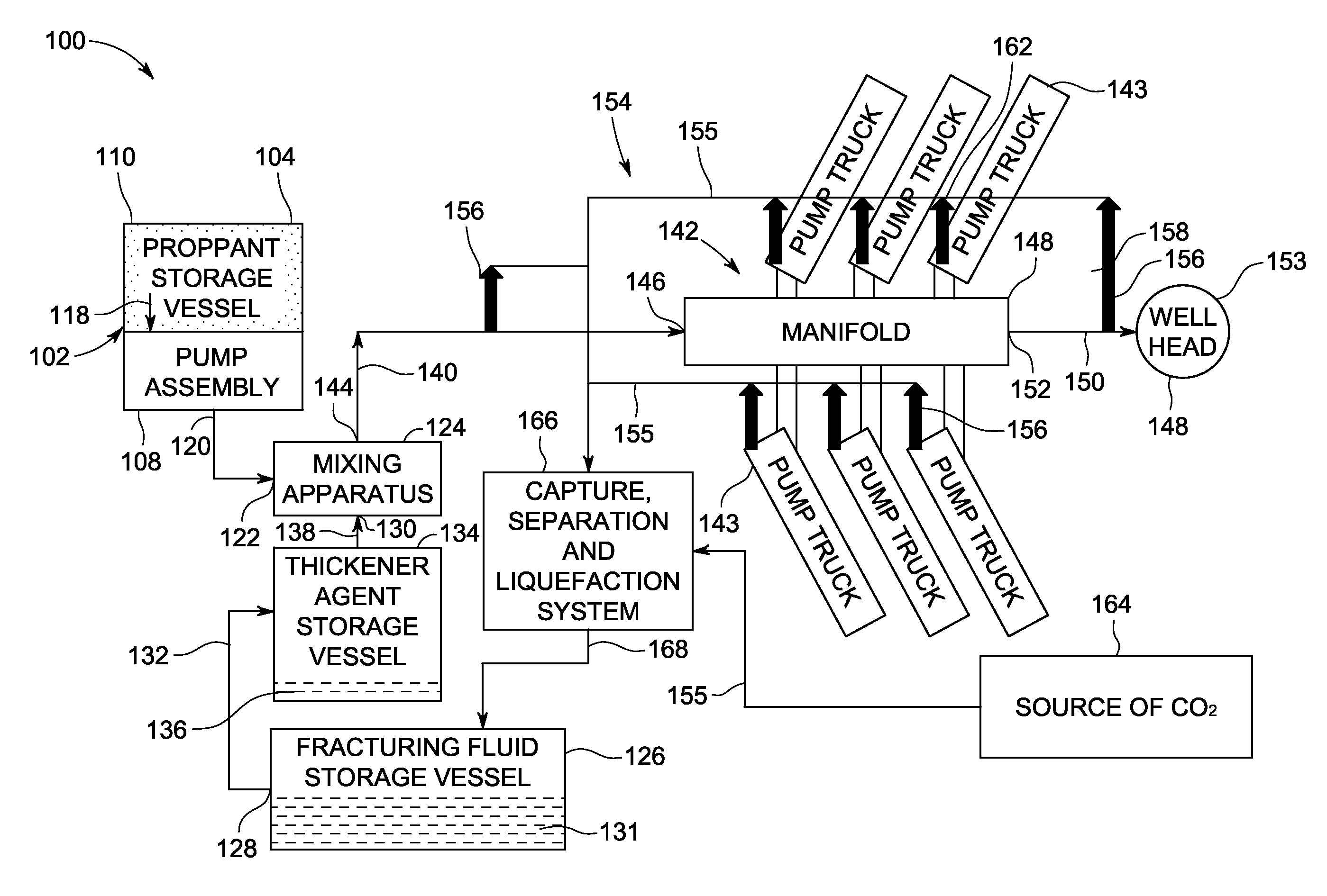
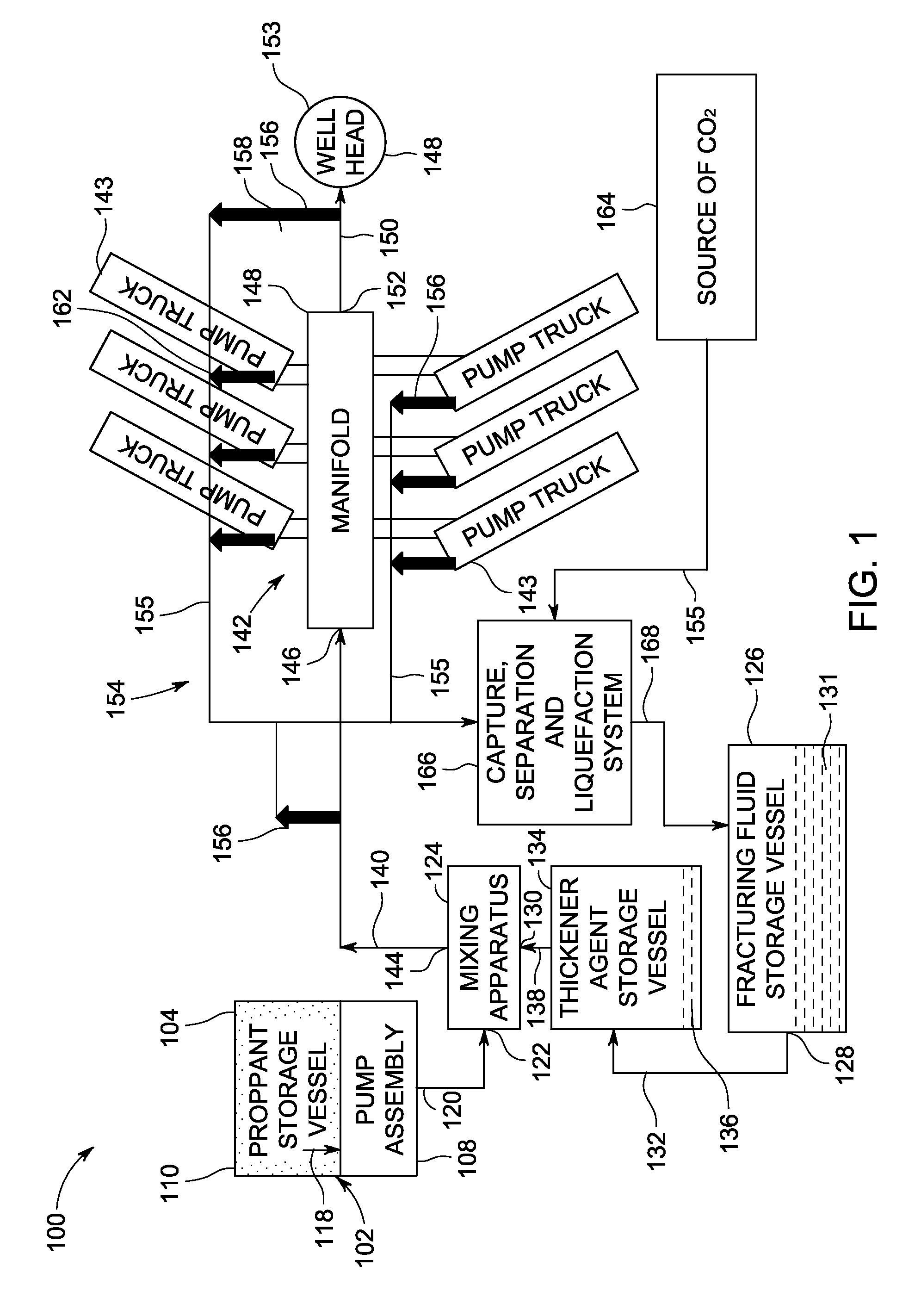
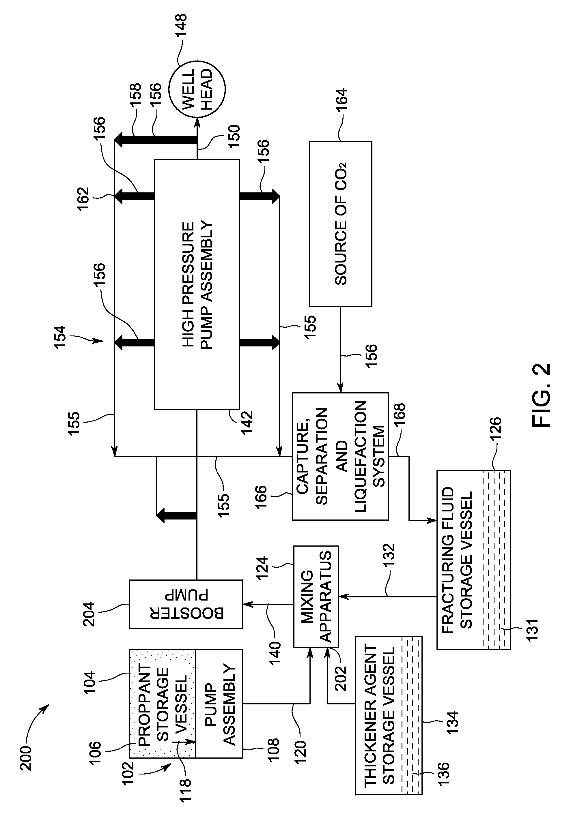
[0017]The invention will be described for the purposes of illustration only in connection with certain embodiments; however, it is to be understood that other objects and advantages of the present disclosure will be made apparent by the following description of the drawings according to the disclosure. While preferred embodiments are disclosed, they are not intended to be limiting. Rather, the general principles set forth herein are considered to be merely illustrative of the scope of the present disclosure and it is to be further understood that numerous changes may be made without straying from the scope of the present disclosure.

[0018]Preferred embodiments of the present disclosure are illustrated in the figures with like numerals being used to refer to like and corresponding parts of the various drawings. It is also understood that terms such as “top”, “bottom”, “outward”, “inward”, and the like are words of convenience and are not to be construed as limiting terms. It is to be ...


PUM


Abstract

An apparatus and method for delivering a thickened fluid mixture, including a CO2 recapture system. The apparatus including a proppant storage vessel and a fracturing fluid storage vessel providing a continuos supply of a proppant material and a fracturing fluid to a mixing apparatus. The mixing apparatus configured to output and deliver a thickened fluid mixture of the proppant, the fracturing fluid and a thickener agent at or above the fracturing fluid blending pressure to a high pressure pump assembly. The high pressure pump assembly configured to deliver a high pressure thickened fluid mixture to one or more downstream components at an injection pressure. The apparatus including a CO2 recapture system configured to recapture an exhaust stream from the one or more downstream components and / or other CO2 output sources, and provide a purified and liquefied CO2 fluid stream to the fracturing fluid storage vessel. The apparatus configured for continual operation.

Description

BACKGROUND[0001]Embodiments disclosed herein relate generally to an apparatus and method of delivering a fluid mixture into a wellbore and recapture / recycling of an output CO2.[0002]Hydraulic fracturing, commonly known as hydro fracturing, or simply fracturing, is a technique used to release petroleum, natural gas or other substances for extraction from underground reservoir rock formations. A wellbore is drilled into the reservoir rock formation, and a treatment fluid is pumped which causes fractures and allows for the release of trapped substances produced from these subterranean natural reservoirs. Current wellhead fracturing systems utilize a process wherein a slurry of fracturing fluid and proppant (e.g. sand) is created and then pumped into the well at high pressure. When water-based fracturing fluids are used, a process referred to as hydro fracturing, the proppant, water and appropriate chemicals can be mixed at atmospheric pressure and then pumped up to a higher pressure fo...

Claims


Application Information

Patent Timeline
Patent Type & Authority Patents(United States)
IPC IPC(8): E21B43/26E21B43/267E21B43/16E21B21/06
CPCE21B43/267E21B21/062E21B43/164
Inventor LISSIANSKI, VITALI VICTORSANBORN, STEPHEN DUANEGORTON, ANDREW JACOB
Owner BAKER HUGHES OILFIELD OPERATIONS LLC
Why Eureka
Try Eureka