Fuel supply device

a fuel supply device and fuel technology, applied in the direction of liquid fuel feeders, machines/engines, mechanical devices, etc., can solve the problems of limited adsorption capacity, waste, and outside the vehicle, and achieve the effect of improving the use efficiency of vaporized fuel

Inactive Publication Date: 2015-09-15
HONDA MOTOR CO LTD
View PDF14 Cites 1 Cited by
  • Summary
  • Abstract
  • Description
  • Claims
  • Application Information

AI Technical Summary

Benefits of technology

[0007]Therefore, it is an object of the present invention to provide a device which supplies fuel to an internal combustion engine while improving the utilization rate of vaporized fuel.
[0011]Moreover, the vaporized fuel derived from the first fuel is sucked from the condenser by the operation of the vacuum pump and thereafter is supplied to the first fuel tank through the first vaporized fuel path. In response to this, at least a part of the vaporized fuel transits in phase from the vapor phase to the liquid phase and is able to be stored as the first fuel in the first fuel tank. In this manner, the vaporized fuel is prevented from being discharged to the outside of a vehicle or the like in an unrecoverable and unusable form at the time of decompression of the condenser, thereby enabling the improvement in the utilization rate of the vaporized fuel.
[0012]Moreover, it is possible to achieve a temporary increase in internal air pressure of the condenser by a temporary switch of the second vaporized fuel path from open to closed. In addition, the kinetic energy of the vaporized fuel leaked out of the first fuel tank through the second vaporized fuel path is able to sweep away the first fuel in the liquid state accumulated in the vacuum pump to the first fuel tank.
[0013]As a result, it is possible to extend the operating time, to decrease the internal air pressure of the condenser, and to restore the vacuum suction function of the vacuum pump which tends to be saturated or decreased along with the retention of the first fuel in the liquid state. This increases the rate of decrease in the internal air pressure of the condenser and enables an increase in the fuel separation frequency or efficiency by the separator.
[0017]According to the fuel supply device having the above configuration, the vaporized fuel filling the first fuel tank is directly or indirectly supplied to the internal combustion engine, thereby enabling the improvement in usage efficiency of the vaporized fuel.

Problems solved by technology

Due to a restriction on a space where the canister is mounted in a vehicle, however, the adsorption capacity is limited.
Accordingly, in the case where a large amount of vaporized fuel occurs, the vaporized fuel which has been unsuccessfully adsorbed to the canister is discharged to the outside of the vehicle and thus wasted.

Method used


Image

  • Fuel supply device
  • Fuel supply device
  • Fuel supply device

Examples


experimental example

[0088]In FIG. 5, there is illustrated a comparison in the recovery efficiency of the first fuel F1 (for example, ethanol) between an example of the present invention and a comparative example. An increased amount of the first fuel F1 in the first fuel tank 40 was measured as a recovery amount of the first fuel F1.

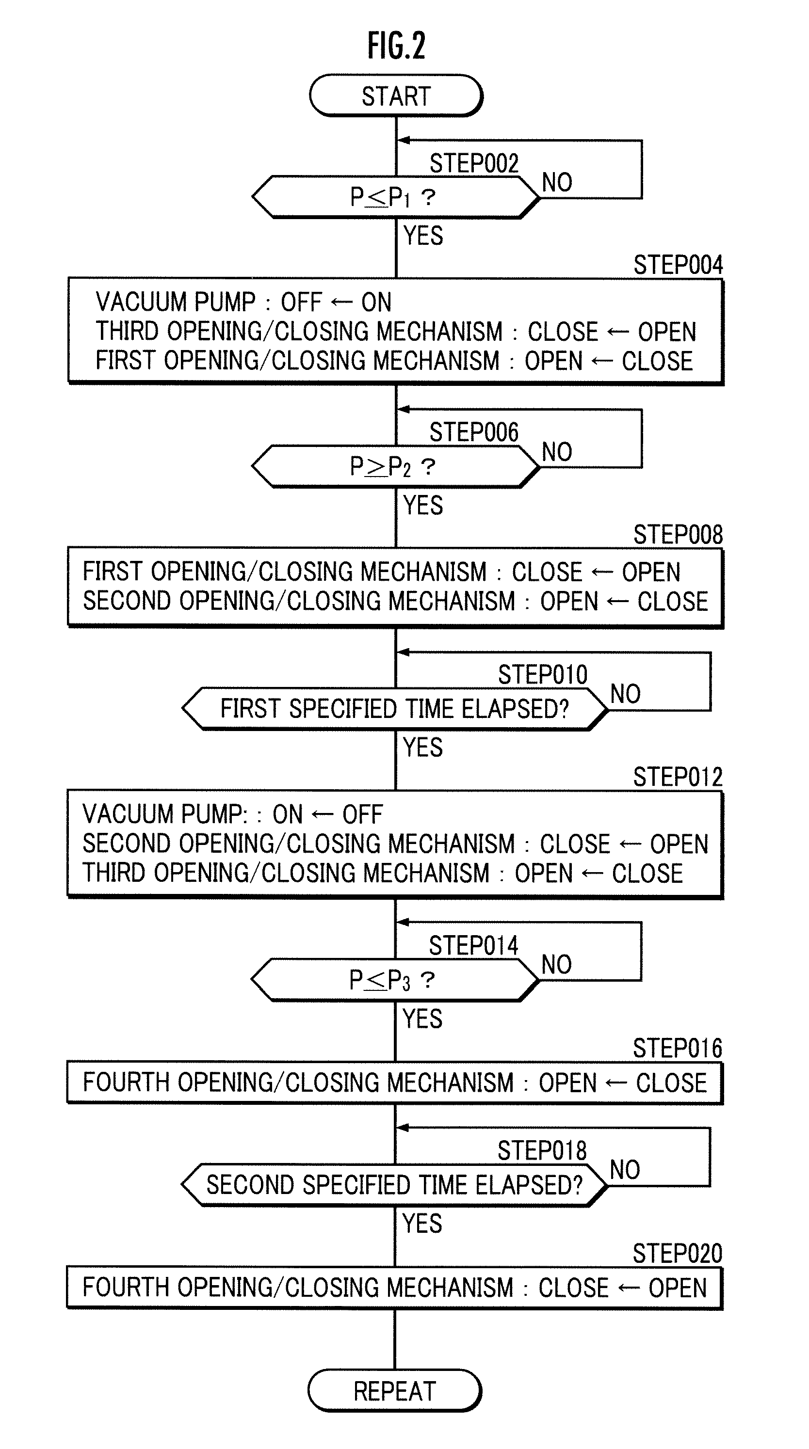
[0089]In the example, the “first state,” the “second state,” and the “third state” were repeatedly achieved as described above, and the negative pressure control processing was performed so that the transition to the “fourth state” is temporarily achieved every time the third state is achieved (See FIG. 2 and FIGS. 3A to 3D).

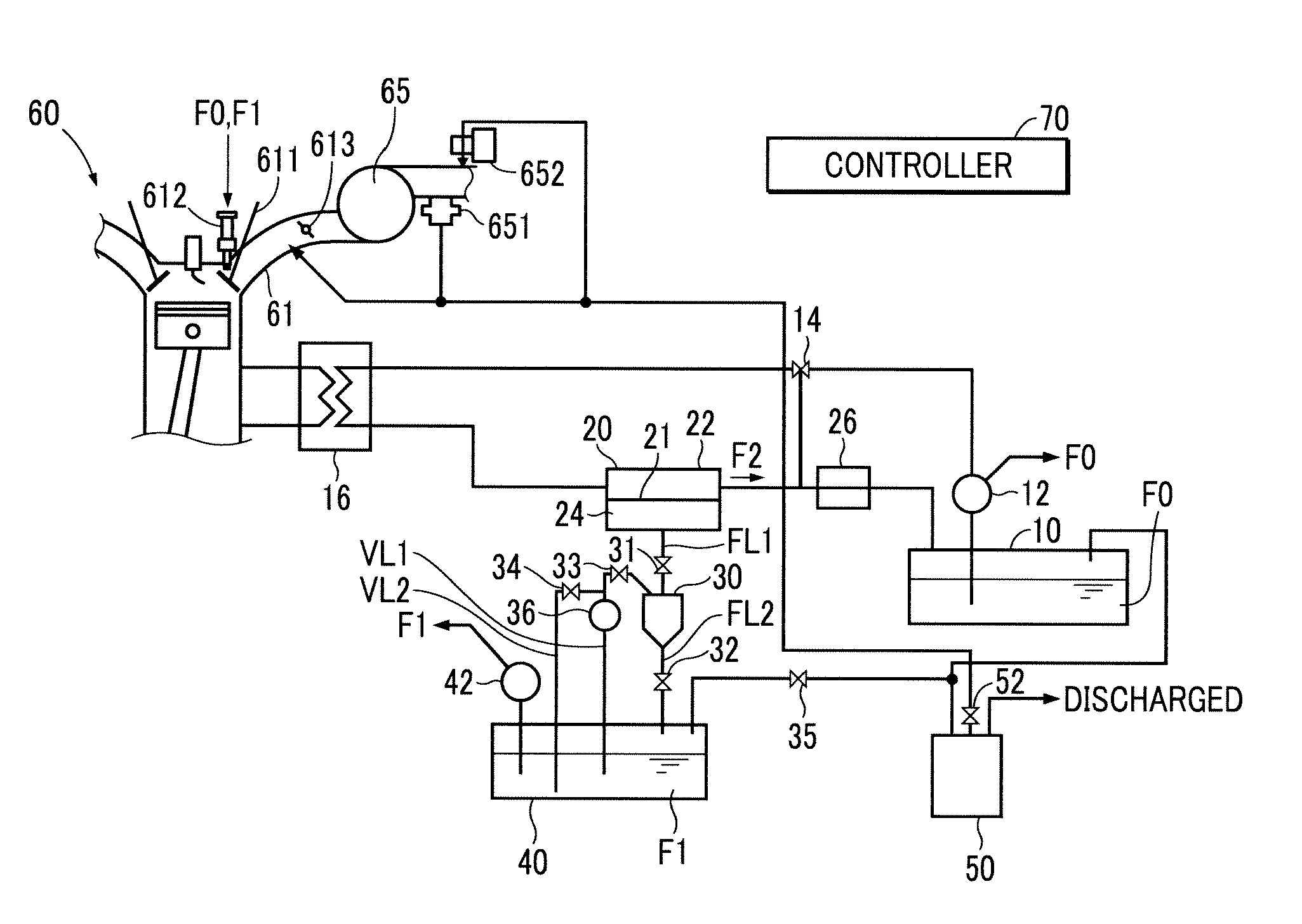
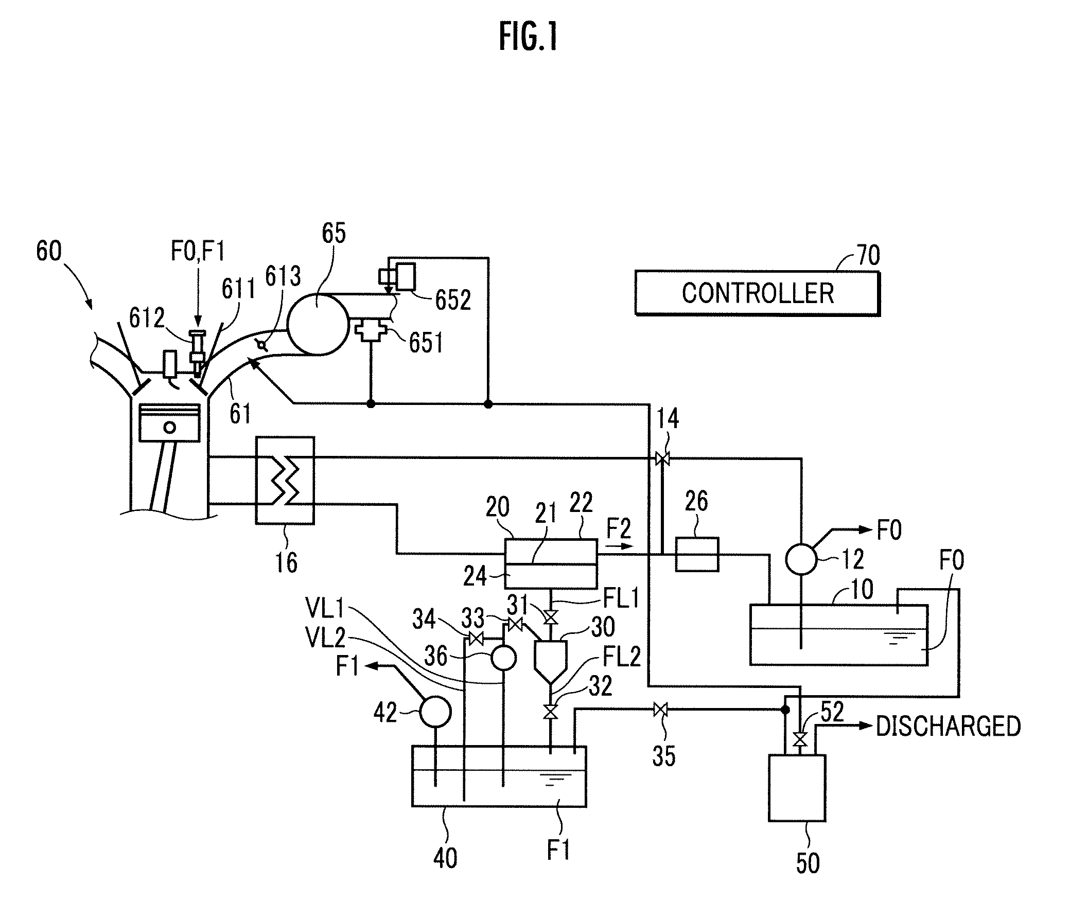
[0090]The comparative example differs from the example in that the second vaporized fuel path VL2 where the fourth opening / closing mechanism 34 is provided does not diverge from the first vaporized fuel path VL1, but is disposed so as to communicate with the first fuel tank 40 directly from the condenser 30. Moreover, the comparative example differs fro...


PUM


Abstract

A device capable of supplying an internal combustion engine with fuel while improving the utilization rate of vaporized fuel. A temporary transition from a third state (primary recovery path FL1: closed, secondary recovery path FL2: closed, second vaporized fuel path VL2: closed, condenser 30: decompressed) to a fourth state (primary recovery path FL1: closed, secondary recovery path FL2: closed, second vaporized fuel path VL2: open, condenser 30: decompressed) is achieved. This temporarily increases an internal air pressure P of a condenser 30, and the kinetic energy of a vaporized fuel V leaked out of a first fuel tank 40 through the second vaporized fuel path VL2 is able to sweep away a first fuel F1 in a liquid state accumulated in a vacuum pump 36 to the first fuel tank 40.

Description

BACKGROUND OF THE INVENTION[0001]1. Field of the Invention[0002]The present invention relates to a technique for supplying fuel to an internal combustion engine.[0003]2. Description of the Related Art[0004]There have been proposed techniques for selectively supplying each of a high octane number fuel and a low octane number fuel separated from a raw fuel to an internal combustion engine (Refer to Japanese Patent Application Laid-Open No. 2007-278298 and Japanese Patent Application Laid-Open No. 2009-144720).[0005]Moreover, there has been proposed a technique for preventing air from entering a tank for storing a high octane number fuel, which is caused by low volatile of the high octane number fuel in comparison with the raw fuel (Refer to Japanese Patent Application Laid-Open No. 2009-203909). Specifically, a device is configured so that vaporized fuel is supplied from a raw fuel tank to the high octane number fuel tank and then supplied from the high octane number fuel tank to a ch...

Claims


Application Information

Patent Timeline
Patent Type & Authority Patents(United States)
IPC IPC(8): F02B43/00F02D19/06F02M43/00F02M25/08
CPCF02D19/0602F02D19/0649F02D19/0665F02M2025/0863Y02T10/36Y02T10/30
Inventor CHISHIMA, HIROSHIKUDO, HIROTSUGUKAWAGUCHI, MASAYOSHISHIGETOYO, KENJI
Owner HONDA MOTOR CO LTD
Why Eureka
Try Eureka