Cable connector with switching structure

a switching structure and cable connector technology, applied in the direction of coupling device connection, coupling prevention, engagement/disengagement of coupling parts, etc., can solve the problems of electrical connection failure, safety risk, and conventional sockets that rarely meet, so as to prevent loosening, prevent loosening, and facilitate connection and assembly. , the effect of convenient replacemen

Active Publication Date: 2015-09-15
T CONN PRECISION CORP
View PDF11 Cites 12 Cited by
  • Summary
  • Abstract
  • Description
  • Claims
  • Application Information

AI Technical Summary

Benefits of technology

[0007]It is an objective of the present invention to provide a cable connector with a switching structure such that the cable connector is hermetically sealed, fixed in place, prevented from loosening, easy to connect and assemble, convenient to change, repair, and disassemble, easy to operate, and for use in engaging with two different types of M12 sockets.

Problems solved by technology

However, due to various extrinsic factors, the connector is likely to get loosened after long-term use to not only cause the cables to separate from each other and thereby cause their electrical connection to fail, but also pose a safety risk.
Furthermore, in attempt to fix connected cable connectors in place, the industrial sector develops different types of sockets and plugs; however, due to specification-related limitations, a type of plugs can match a single type of sockets only.
Referring to FIG. 10, not only does a conventional socket seldom meet the high-efficiency and multifunction requirements expected by a modernized industrial society, but the conventional socket is also likely to undergo material fatigue and structural wear after long-term use and thereby deteriorate its tight-fitting matching function.
After long use, the coil spring undergoes resilience failure or displacement and thus results in deterioration of coupling stress, thereby losing the switching and snap-engaging function.
Furthermore, after the connector has got loosened, power transmission interruption is likely to occur, thereby posing a safety risk.
Moreover, the coil spring is disposed in an inner cavity of the plug and thus renders it inconvenient to assemble, install, disassemble, and repair the cable connector, thereby failing to meet the requirements of convenience and high efficiency.

Method used


Image

  • Cable connector with switching structure
  • Cable connector with switching structure
  • Cable connector with switching structure

Examples


first embodiment

[0051]Referring to FIGS. 5A, 5B, there are shown left and right lateral views of the cable connector of the present invention, a conventional socket, and the caulking portion-free socket holder after the assembly process according to the present invention, respectively. As shown in the diagrams, to allow the plug 1 and the plug holder 2 to be coupled to the conventional socket 3 and the socket holder 4 free of a caulking portion, the user pushes the lever 221 leftward (viewed from the end of the socket holder 4 free of a caulking portion,) such that the at least a leaf spring 222 moves to one side within the second slot 212, wherein the protuberance 25 is absent from the one side within the second slot 212 (as shown in FIG. 4A.) The switch ring 22 is fixed to the inner cavity of the plug holder 2 by means of the fastening nut 26. The lever 221 is disposed in the first slot 211 (as shown in FIG. 2A.) The bend portion 226 at the rear end of the lever 221 abuts against the protuberance...

third embodiment

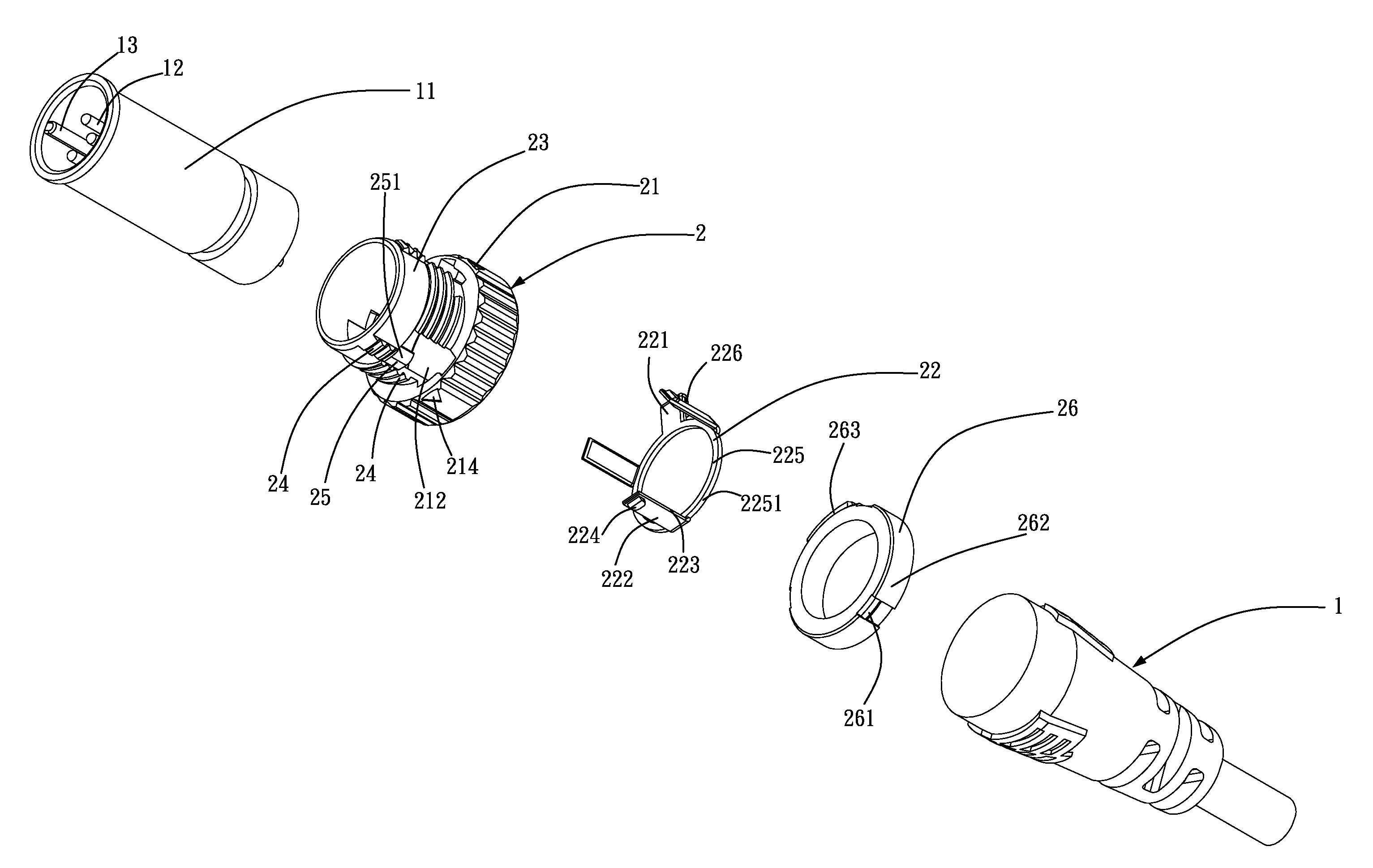
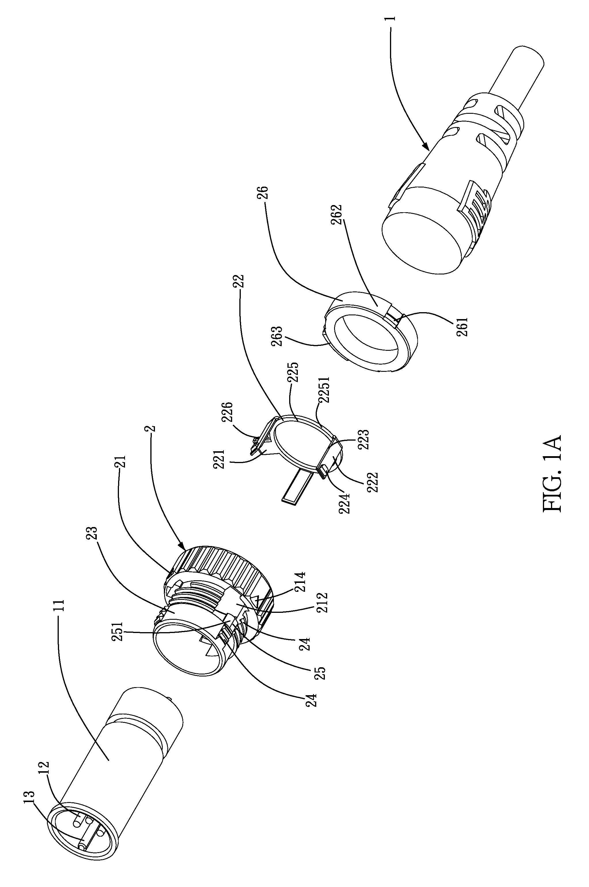
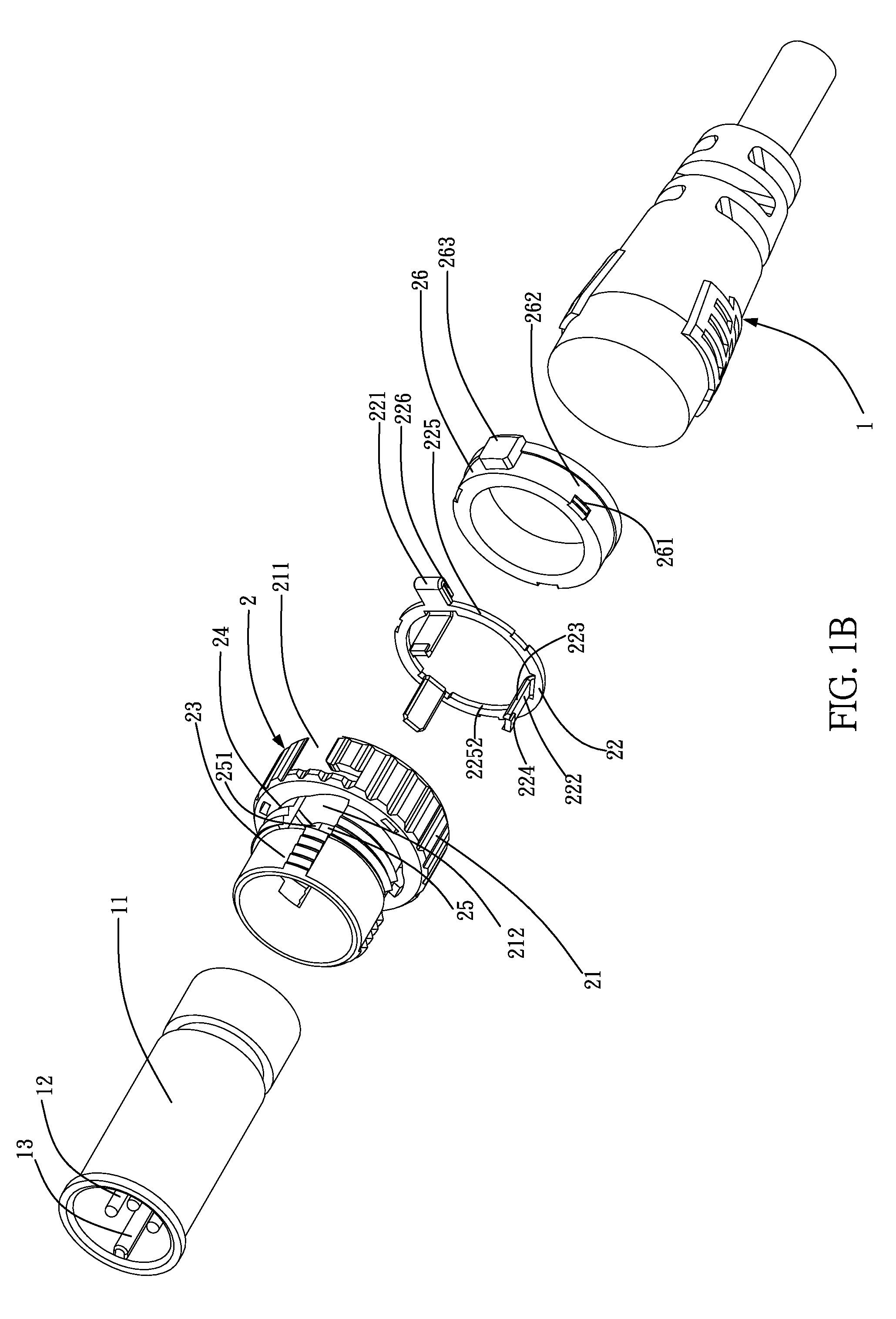
[0058]In the present invention, a plug with a switching structure comprises a plug 1 and a plug holder 2. The plug 1 has a plug rubber core 11. The plug rubber core 11 has pin terminals 12 and a rib 13. The plug holder 2 has a grip portion 21 with ridges and a switching structure disposed around the grip portion 21. The switching structure comprises a switch ring 22 and a fastening nut 26. The switch ring 22 and the fastening nut 26 are formed integrally as a unitary structure. The plug holder 2 is disposed around the surface of the plug 1. The plug holder 2 is coupled to the socket holders 4, 6 of different types by means of the switch ring 22.

fourth embodiment

[0059]In the present invention, a plug with a switching structure comprises a plug 1 and a plug holder 2. The plug 1 has a plug rubber core 11. The plug rubber core 11 has pin terminals 12 and a rib 13. The plug holder 2 has a grip portion 21 with ridges and a switch ring 22 disposed around the grip portion 21. The plug holder 2 is disposed around the surface of the plug 1. The plug holder 2 is coupled to the socket holders 4, 6 of different types by means of the switch ring 22.

[0060]In conclusion, a cable connector with a switching structure provided according to the present invention fulfills the objectives thereof, as the cable connector with a switching structure is hermetically sealed, fixed in place, prevented from loosening, easy to connect and assemble, convenient to change, repair, and disassemble, easy to operate, and for use in engaging with two different types of M12 sockets.


PUM


Abstract

Provided is a cable connector with a switching structure, including: a plug with a plug rubber core having a plurality of pin terminals and a rib; and a plug holder having a grip portion with ridges, a switch ring disposed around the grip portion, and a fastening nut abutting against the switch ring, wherein the plug holder is disposed around the plug, and the plug holder is coupled to sockets of different types by means of the switch ring. Therefore, the cable connector is hermetically sealed, fixed in place, prevented from loosening, easy to connect and assemble, convenient to change, repair, and disassemble, easy to operate, and for use in engaging with two different types of cable sockets.

Description

BACKGROUND OF THE INVENTION[0001]1. Technical Field[0002]The present invention relates to cable connectors each with a switching structure, and more particularly, to a cable connector equipped with a switching structure and intended for use with a power line or a signal line.[0003]2. Description of Related Art[0004]A conventional cable connector connects a cable to any device. Due to technological advancement, plenty connectors are continually developed to enable users to perform quick connection, and increasingly great importance is attached to protection for cable connectors. In this regard, however, in the course of connecting to cables, a connector not only has to manifest basic satisfactory electrical connection characteristics, but the connector body also has to feature a specific bonding stress. However, due to various extrinsic factors, the connector is likely to get loosened after long-term use to not only cause the cables to separate from each other and thereby cause their...

Claims


Application Information

Patent Timeline
Patent Type & Authority Patents(United States)
IPC IPC(8): H01R13/642H01R13/627H01R27/00H01R13/641H01R13/622H01R107/00
CPCH01R27/00H01R13/6275H01R13/622H01R13/641H01R2107/00
Inventor CHANG, WEIYU, CHIEN-YI
Owner T CONN PRECISION CORP
Why Eureka
Try Eureka