Hole-making tool

a tool and hole technology, applied in manufacturing tools, cutting inserts, transportation and packaging, etc., can solve the problems of affecting the quality of the tool, the need to retract the tool through the machined hole, and the damage to the surrounding hole surface, so as to avoid the need for removing the tool from the hol

Inactive Publication Date: 2015-09-22
SANDVIK INTELLECTUAL PROPERTY AB
View PDF12 Cites 2 Cited by
  • Summary
  • Abstract
  • Description
  • Claims
  • Application Information

AI Technical Summary

Benefits of technology

[0005]The present invention provides a hole-making tool, which allows reversal or retraction of the tool from a hole without damaging the hole surface or making the retraction more difficult. Therefore, a primary object of the invention is to provide a hole-making tool having one or more peripherally mounted cutting inserts, which in a reliable way resist such forces that aim to remove the cutting insert axially out of the seat during reversal of the direction of motion of the tool, and such forces that aim to separate the cutting insert from the radial support surface of the seat. It is also an object to provide a hole-making tool that is simple and inexpensive to manufacture. In a particular aspect, the invention aims at providing a hole-making tool that has a long service life even if not only a cutting insert, but also an appurtenant seat would be damaged. In other words, the tool should not need to be discarded in its entirety if a seat of a cutting insert is demolished.
[0009]In one embodiment, the female-like securing means is formed in the underside of the cutting insert, while the male-like securing means is included in the tangential support surface of the seat. An advantage of this embodiment is that the manufacture of the cutting insert, as well as of the seat for the same is facilitated. For pressing technical reasons, the cutting insert becomes stronger if the same is formed with female-like countersinks than with male-like projections.
[0011]In one embodiment, the securing means may be a stud that projects from the tangential support surface and is in line contact with the guide surface rather than the surface contact. In such a way, the risk of inadequate tolerances disturbing the function of the securing means is eliminated.
[0012]Furthermore, it is feasible to form the male-like securing means, irrespective if it is a ridge or a stud, in the form of an inset, which can be mounted in a countersink mouthing in the tangential support surface. In such a way, the manufacture of the seat in the basic body is facilitated, at the same time as the solution affords the possibility of using different materials, in particular different steel no grades, in the male-like securing means and the basic body, respectively. For instance, the male-like securing means may be manufactured from a steel that is harder than the steel of the basic body.
[0014]According to another embodiment, the angle between the guide surface of the female-like securing means and the radial support surface of the seat is selected to a value of at least 20° and at most 70°. In such a way, it is guaranteed, on one hand, that the cutting insert, after a possible activation of the securing means, is pressed against the radial support surface by considerable force, and on the other hand that the activation of the securing means occurs at optimum speed.
[0015]In one embodiment of the invention, the interface between the underside of the cutting insert and the tangential support surface of the seat is formed with not only a first pair of co-operable female- and male-like securing means, but also with a second pair located between the radial support surface and the first pair. In such a way, it is guaranteed not only that the cutting insert is reliably pressed against the radial support surface, but also that axial displacement of the cutting insert in the direction from the axial support surface is efficiently prevented.

Problems solved by technology

However, also in the first case, the need of retracting the tool through the machined hole may arise, for instance if one or more cutting inserts become damaged or come loose from the tool, or that the driving machine facility stops.
Irrespective of whether a retraction of the tool from the hole is intentional or unintentional, problems may arise so far that the surrounding hole surface risks being damaged by peripherally situated cutting inserts.
At times, difficulties when removing the tool from the hole also occur.
Damage to the hole surface is generally undesired.
In the worst case, the same may cause rejections of expensive components.
However, the securing means of the disclosed tool are only intended to counteract axial displacement of the cutting insert out of the seat, but not to prevent the cutting insert from moving in the direction radially out of the seat.
Even if the securing means generally guarantee that the cutting insert remains in the seat, the same do not prevent or counteract the cutting insert from moving radially outward; which may give cause scratches or other damage in the generated hole surface.

Method used


Image

  • Hole-making tool
  • Hole-making tool
  • Hole-making tool

Examples


Embodiment Construction

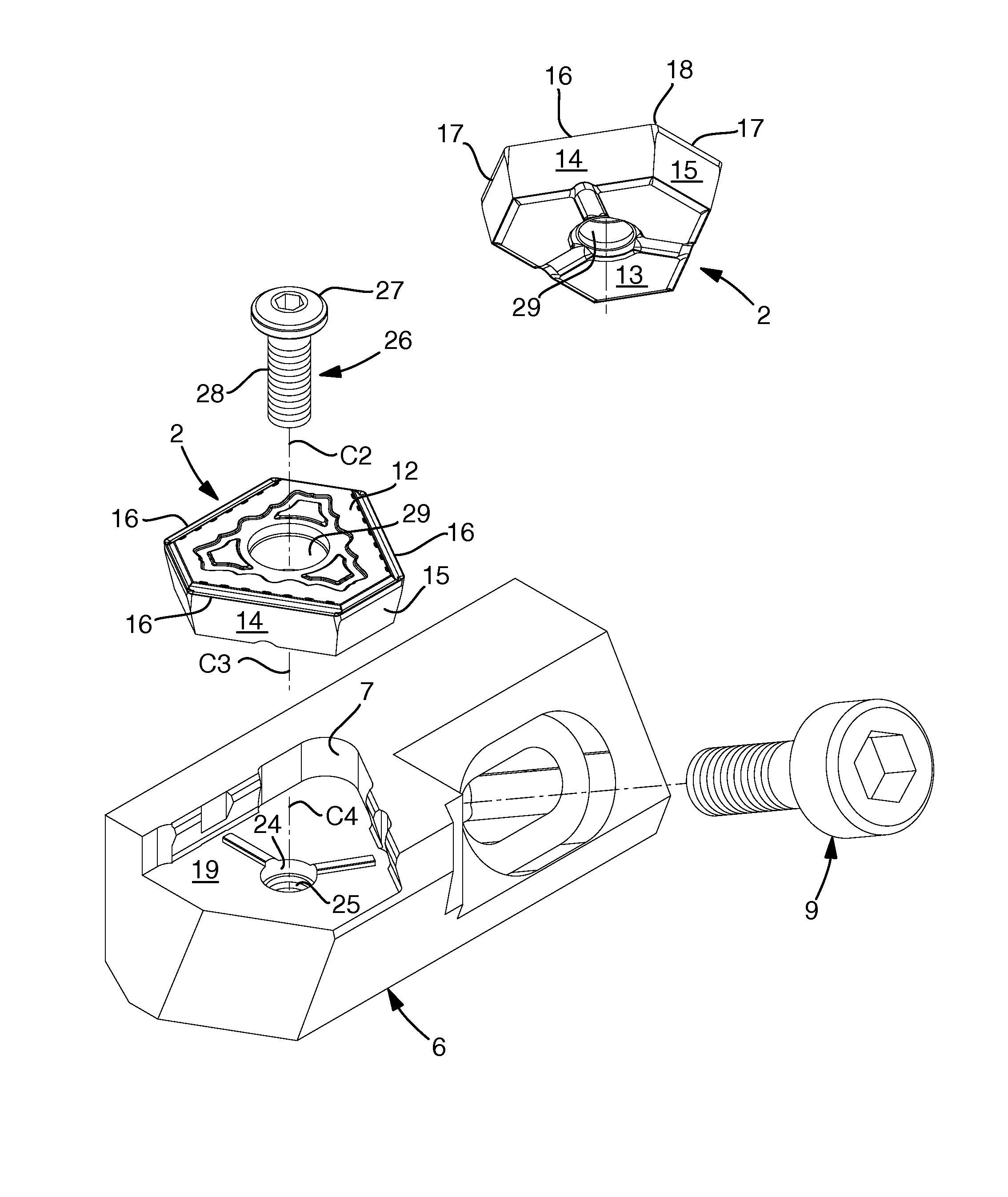
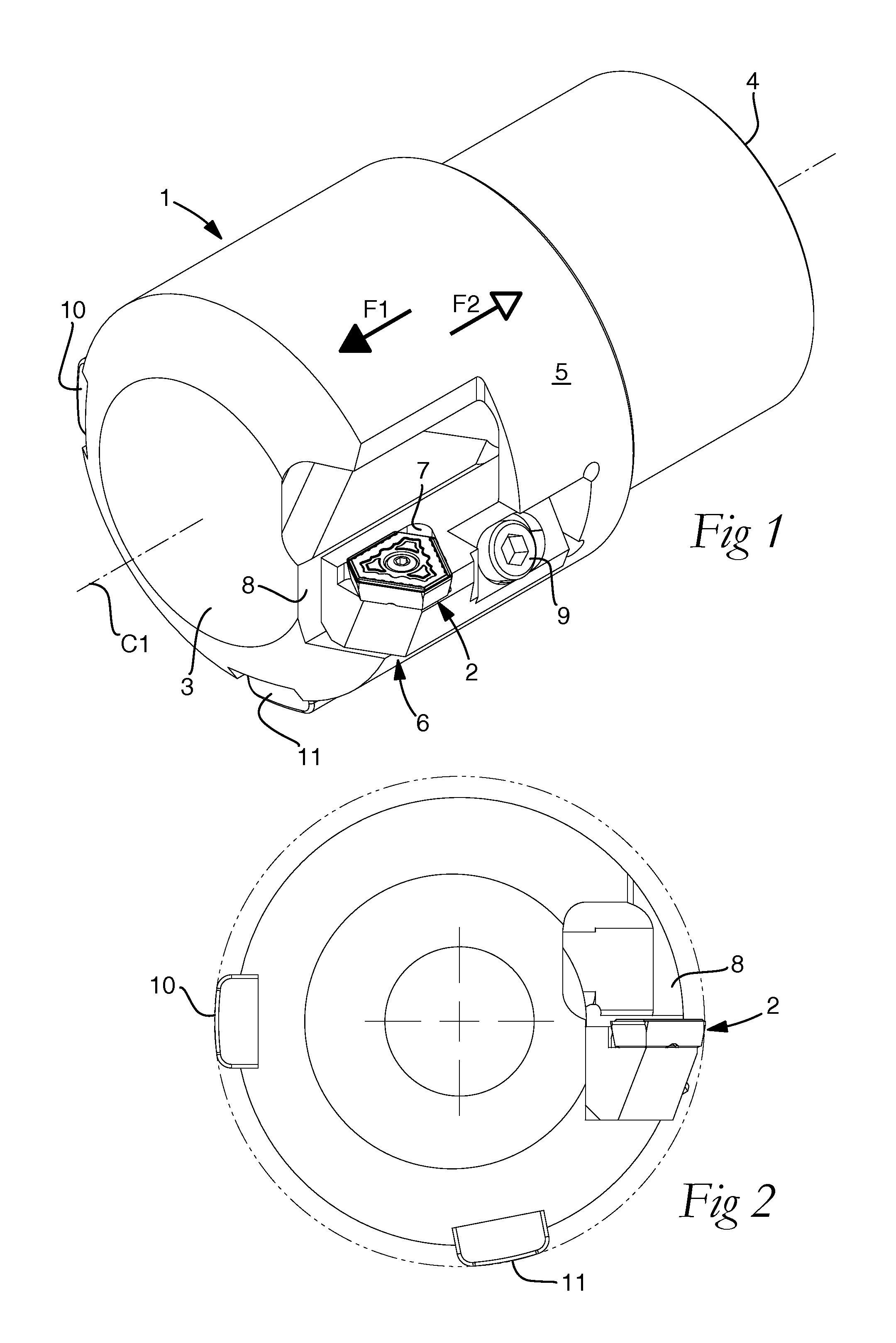
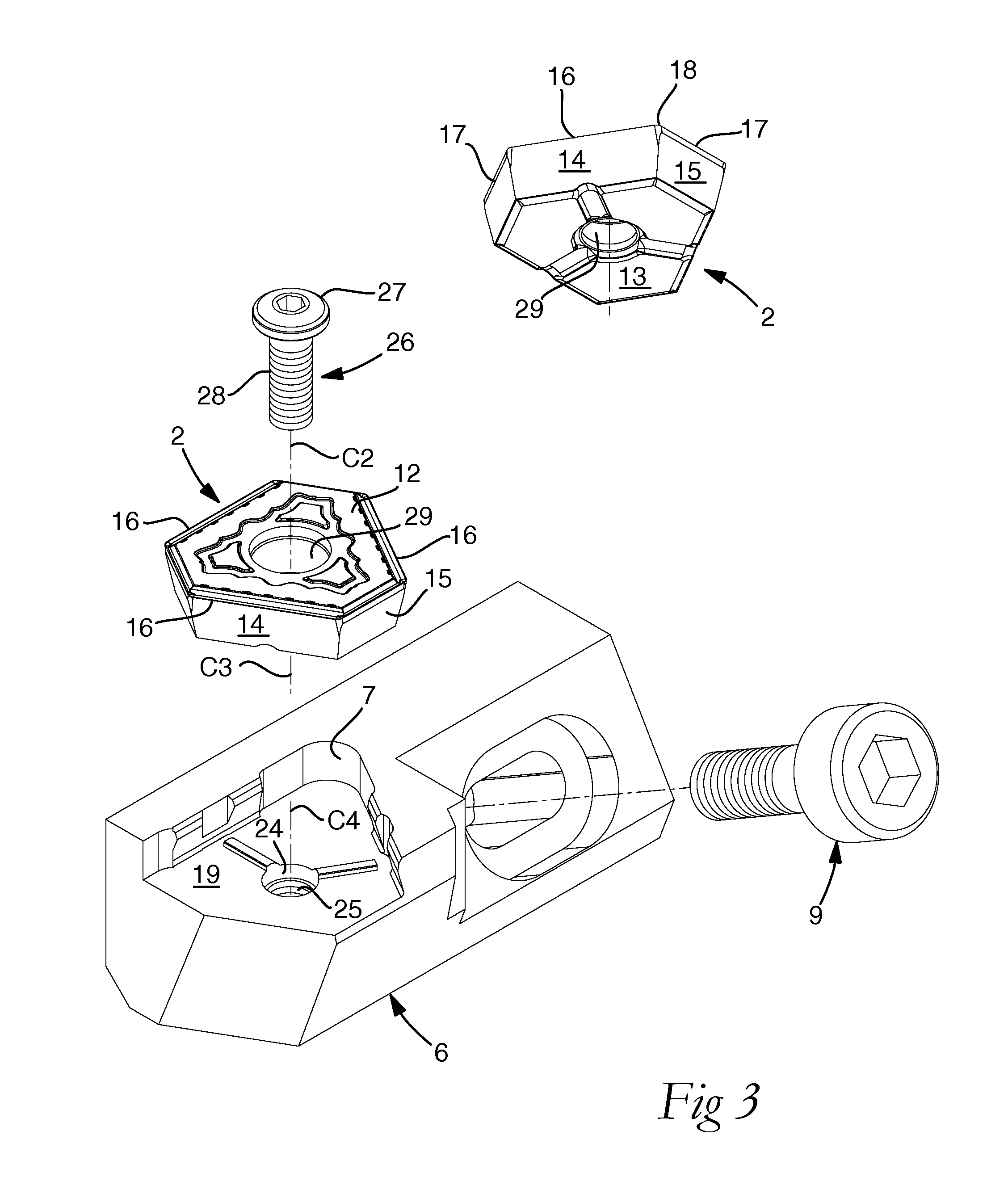
[0027]In FIGS. 1 and 2, a hole-making tool is shown in the form of a reamer, which includes a head 1 and a replaceable cutting insert 2. The head 1 includes front and rear ends 3, 4 between which a center axis C1 of the tool extends, with which a rotationally symmetrical envelope surface 5 is concentric and on which the head can, if required, be rotated. To the head 1, a cassette 6 is detachably connected, in which a seat 7 for the cutting insert 2 is formed. The cassette 6 is mounted in a pocket 8 that is countersunk in the envelope surface 5 and opens in the front end of the head. The cassette 6 is held fixed in the pocket by means of a bolt 9. As shown in FIGS. 1 and 2, a pair of support and guide pads 10, 11 are tangentially spaced-apart from the solitary cutting insert 2, in order to, together with the same, provide a three-point support for the tool during the reaming of a (pre-drilled) hole, which is indicated by means of a dash-dotted circular line in FIG. 2. In FIGS. 1, F1 ...


PUM

PropertyMeasurementUnit
angleaaaaaaaaaa
angleaaaaaaaaaa
angleaaaaaaaaaa

Abstract

A hole-making tool includes a body having a seat, which is delimited by a tangential support surface, an axial support surface, and a radial support surface. A cutting insert is fixed in the seat. A pair of female- and male-like securing means is arranged in the interface between the tangential support surface of the seat and the underside of the cutting insert. The female-like securing means includes a guide surface. The male-like securing means is spaced from the guide surface to form a gap between the securing means when the cutting insert is pressed against the axial and radial support surfaces. If the feeding direction of the tool is reversed, the cutting insert may become detached from the seat and the securing means is activated to direct the cutting insert inward toward the radial support surface to prevent the peripheral portion of the cutting insert from scratching the generated hole.

Description

RELATED APPLICATION DATA[0001]This application claims priority under 35 U.S.C. §119 to Swedish Patent Application No. 1250035-1, filed on Jan. 20, 2012, which the entirety thereof is incorporated herein by reference.TECHNICAL FIELD OF THE INVENTION[0002]This invention relates to a hole-making tool of the type that includes a basic body having a seat delimited by a tangential support surface, an axial support surface, and a radial support surface. The support surface is situated closest to a center axis of the tool. The hole-making tool also includes a replaceable cutting insert, which has an upper side and an under side, and a plurality of side contact surfaces. The cutting insert is fixed in the seat by a tightening member, which holds the underside of the cutting insert pressed against the tangential support surface of the seat and holds two side contact surfaces against the axial and radial support surfaces thereof.BACKGROUND OF THE INVENTION[0003]Hole making or drilling generall...

Claims


Application Information

Patent Timeline
Patent Type & Authority Patents(United States)
IPC IPC(8): B23B51/00B23B51/04B23C5/22B23B27/16B23D77/02
CPCB23B51/048B23B27/1622B23C5/2221B23C5/2226B23D77/025B23B51/00B23B2200/161B23B2200/165B23B2205/12B23B2251/50B23C2200/165B23C2210/168B23D2277/84Y10T408/89Y10T408/9098B23C5/2213B23B51/0018
Inventor HANSSON, PER
Owner SANDVIK INTELLECTUAL PROPERTY AB
Why Eureka
Try Eureka