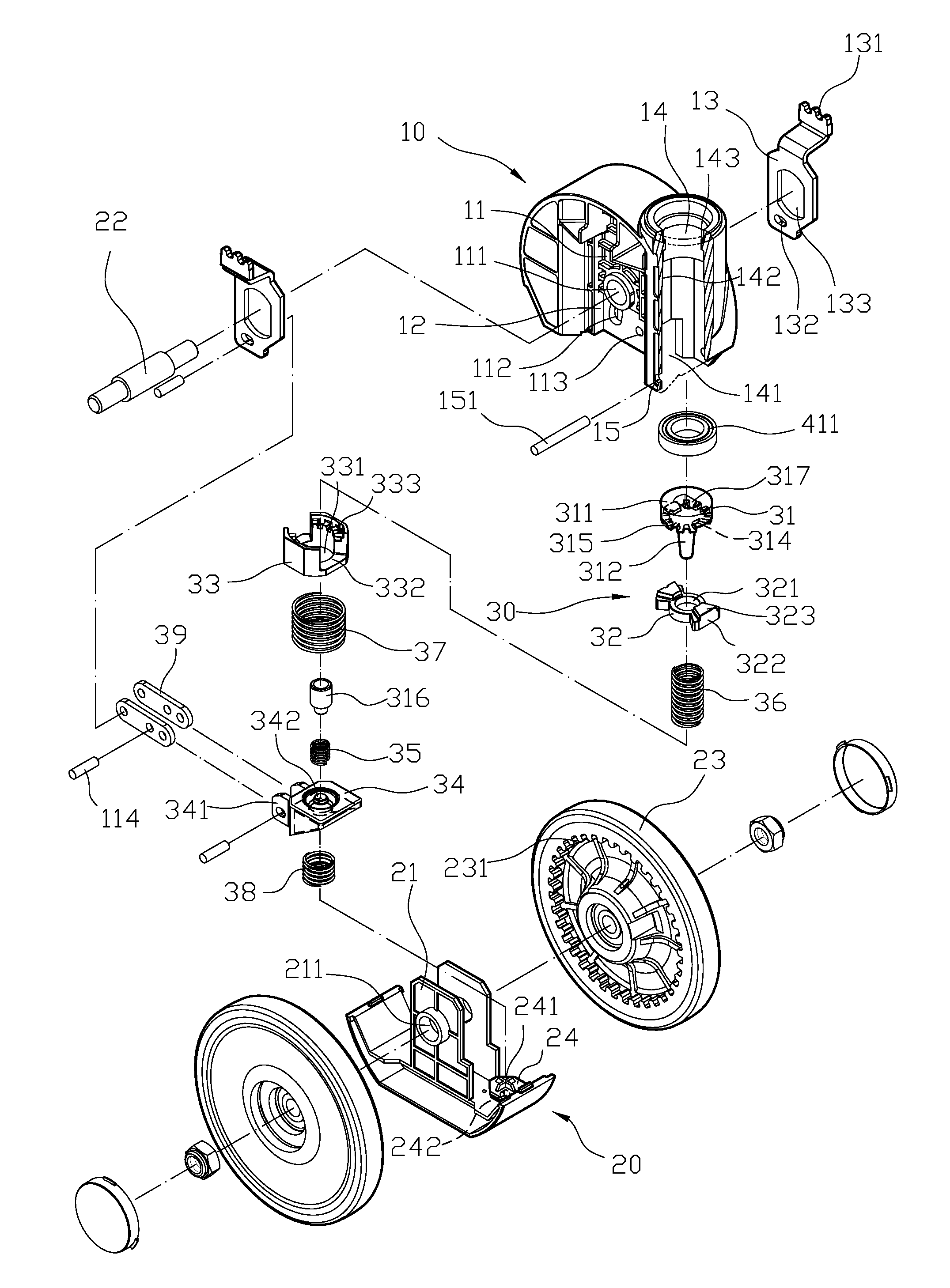
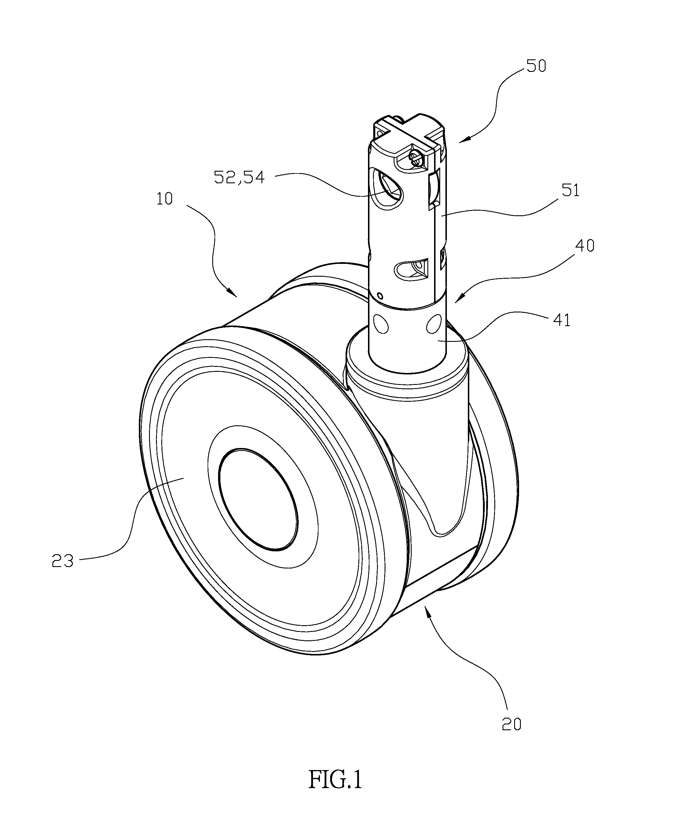
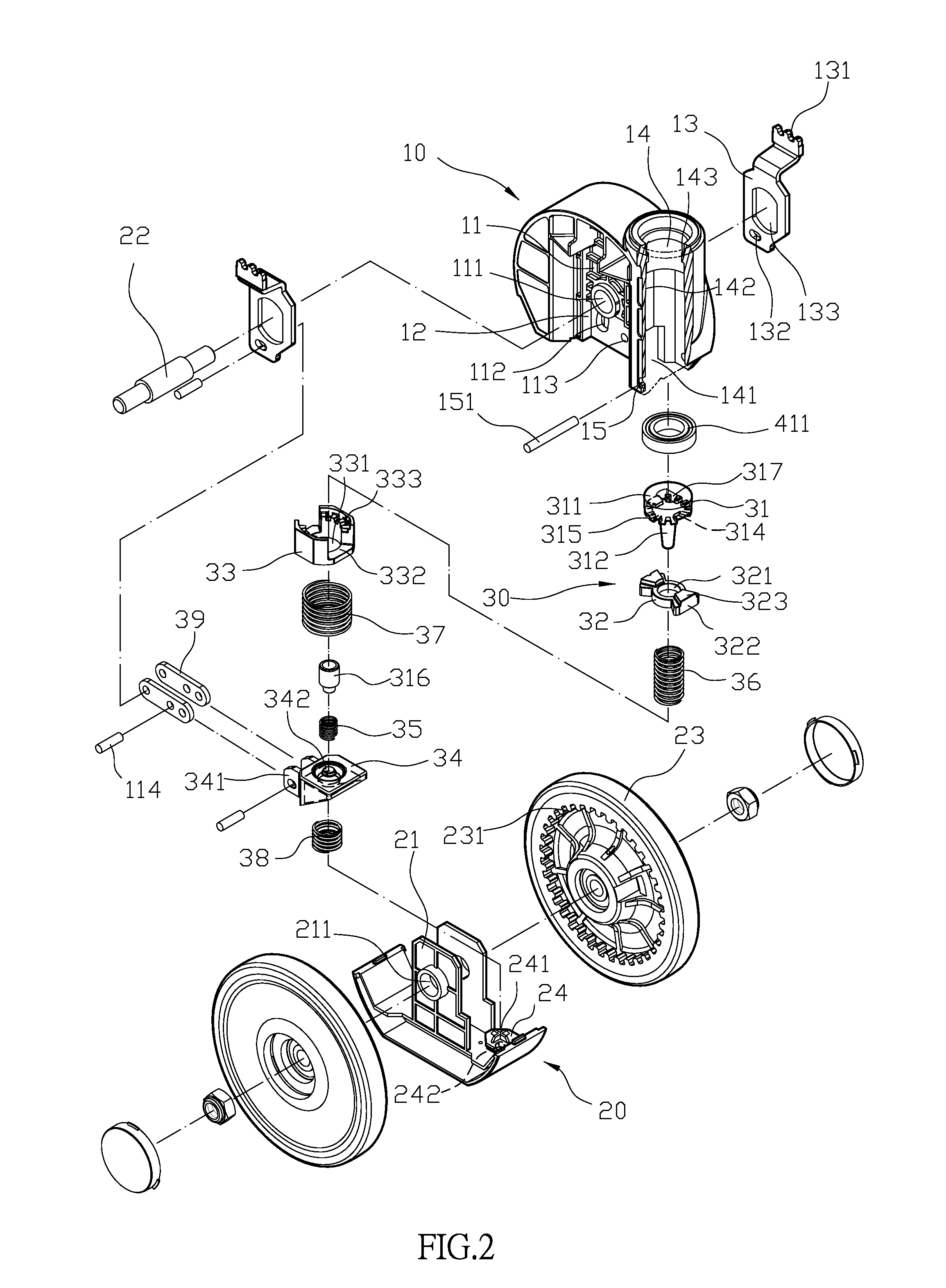
Central-controlled double wheel structure

a technology of central control and double wheels, which is applied in the direction of castors, vehicle components, transportation and packaging, etc., can solve the problems of increasing the gap between the surface of the wheel body and the braking pad, reducing the thickness of the baking pad and the wheel body, and reducing so as to effectively stop the rotational movement increase the life of the wheel body, and increase the performance accuracy of the direction positioning structure

Inactive Publication Date: 2015-09-22
DERSHENG
View PDF17 Cites 17 Cited by
  • Summary
  • Abstract
  • Description
  • Claims
  • Application Information

AI Technical Summary

Benefits of technology

[0003]As previously described, the wheel bodies of the current commercial available wheel structures are subjected to severe wear caused by fraction between the braking pads and the wheel bodies when the braking operation is frequently needed, which reduces the thickness of the baking pads and the wheel bodies and increases the gap between the surfaces of the wheel bodies and the braking pads. As a result, the braking operation may not be properly performed as the braking pad may not properly contact the surface of the wheel body and the transporting devices equipped with this wheel structure may not be stopped effectively. This defect may be corrected by replacing the non-functional wheel, however it may incur extra costs and is inconvenient in practical uses. The present invention provides a central-controlled double wheel structure with novel structural design, increased structural strength, and desirable stability that solves the abovementioned problems of current wheel structure.
[0005]The above described structural design of the central-controlled wheel structure of the present invention provides multiple advantages over conventional ones. For example, the cooperated function of the braking block of the braking component together with the direction limiting member and the toothed braking member to allows the wheel structure to achieve proper relative positioning of the upper base and the control component. Further, the position limiting bulged portion of the positioning member and the cogging portions of the toothed braking member mutually restrict each other's positioning, together with the intermeshing effects between the position limiting bulged portion and the position limiting recessed portions of the braking block, as well as between the cogging portions and the toothed cogging area of the braking member, allow the direction limiting member, and the toothed braking member to be stably intermeshed, which in turn increases the performance accuracy of the direction positioning structure, and ensures the central-controlled double wheel structure to move strictly following a preset straight direction, without being distracted by external forces.
[0006]Also, the braking pads that are installed between the upper base and the lower base are connected to the bridging plates, and as a result the positioning of the braking pads can be controlled of the upward or downward movement of the connecting seat. This is achieved as the partitioning board of the upper base has an axial hole which allows the interposition of an axial rod to connect with the bridging plates, and therefore the bridging plates may act as a lever structure and undergo rotational movement with the axial rod as the axis. Further, the wheel bodies of the lower base have a set of cogging teeth located at the inner walls of the wheel bodies corresponding to the positions of the serrated card ends of the braking pads, allowing the serrated cogging ends of the braking pads to be intermeshed into the sets of cogging teeth of the wheel bodies to effectively stop the rotational movement of the wheel bodies. Further, the structural components involved in the braking operation are not subjected to wearing, and as a result the central-controlled double wheel structure of the present invention has an extensively increased life span which is highly desirable in practical uses.

Problems solved by technology

As previously described, the wheel bodies of the current commercial available wheel structures are subjected to severe wear caused by fraction between the braking pads and the wheel bodies when the braking operation is frequently needed, which reduces the thickness of the baking pads and the wheel bodies and increases the gap between the surfaces of the wheel bodies and the braking pads.
As a result, the braking operation may not be properly performed as the braking pad may not properly contact the surface of the wheel body and the transporting devices equipped with this wheel structure may not be stopped effectively.
This defect may be corrected by replacing the non-functional wheel, however it may incur extra costs and is inconvenient in practical uses.

Method used


Image

  • Central-controlled double wheel structure
  • Central-controlled double wheel structure
  • Central-controlled double wheel structure

Examples


Embodiment Construction

[0015]The detailed description set forth below is intended as a description of the presently exemplary device provided in accordance with aspects of the present invention and is not intended to represent the only forms in which the present invention may be prepared or utilized. It is to be understood, rather, that the same or equivalent functions and components may be accomplished by different embodiments that are also intended to be encompassed within the spirit and scope of the invention.

[0016]Unless defined otherwise, all technical and scientific terms used herein have the same meaning as commonly understood to one of ordinary skill in the art to which this invention belongs. Although any methods, devices and materials similar or equivalent to those described can be used in the practice or testing of the invention, the exemplary methods, devices and materials are now described.

[0017]All publications mentioned are incorporated by reference for the purpose of describing and disclos...


PUM


Abstract

A central-controlled double wheel structure allows accurate performance in controlling the direction of movement of transporting devices when a braking block, a direction limiting member, and a toothed braking member are stably and properly intermeshed, thereby ensuring transporting devices to move in a preset straight direction. The double wheel structure has braking pads that are connected to bridging plates which are in turn connected to a connecting seat, and positioning of the braking pads is controlled by the upward or downward movement of the connecting seat as the bridging plates act as a lever structure with the axial rod as the axis. Further, the serrated cogging ends of the braking pads may intermesh into the cogging teeth of the wheel bodies to effectively stop the movement of transporting devices without subjecting the braking pads and the wheel bodies to extensive wearing.

Description

FIELD OF INVENTION[0001]The present invention relates to a wheel structure, more specifically a central-controlled double wheel structure.BACKGROUND OF THE INVENTION[0002]Most conventional wheel structure allows only for braking, and only a small portion used for medical purposes may allow wheel structure move toward a straight direction. However, although both the direction positioning component and the braking component of these specialized carts are usually installed to the wheel structure and are operated by foot pedals, the direction positioning component however needs to be controlled separately from the braking component, which is rather inconvenient. A different type of wheel structure that is commercially available have an improved controlling structure which allows the wheel structure to rotate freely, to move in a preset straight direction, and to be stopped by a braking operation, and thus the transporting devices equipped with this type of improved wheel structure posse...

Claims


Application Information

Patent Timeline
Patent Type & Authority Patents(United States)
IPC IPC(8): B60B33/06B60B33/00
CPCB60B33/0028B60B33/0047B60B33/0042B60B33/0086B60B33/0092B60B33/021B60B33/025B60B33/026B60B2900/112B60B2900/113B60B2900/323
Inventor FAN, TSO-YU
Owner DERSHENG
Why Eureka
Try Eureka