System with a suspension device and a rail

a suspension device and rail technology, applied in the direction of conveyors, load-engaging elements, ways, etc., can solve the problems of small cross-section reduction in the threaded rod, barely reducing its strength, etc., and achieve the effect of simplifying and ensuring assembly

Active Publication Date: 2015-09-22
KONECRANES GLOBAL
View PDF23 Cites 3 Cited by
  • Summary
  • Abstract
  • Description
  • Claims
  • Application Information

AI Technical Summary

Benefits of technology

[0005]The present invention provides a suspension device for a rail, in particular a running rail of an overhead conveyor or a lifting gear, which allows simplified and secure assembly.
[0006]In accordance with an embodiment of the invention, in the case of a suspension device for a rail, in particular a rail of an overhead conveyor or a lifting gear, having a tensile element which includes a threaded rod and at least one connection part screwed thereto, and having a securing element which prevents the screw connection between the threaded rod and the connection part from being loosened, simplified and secure assembly is achieved by virtue of the fact that the securing element engages with a pin part into a groove in the assembled state, said groove being disposed in the threaded rod. The groove in the threaded rod results in considerably simpler assembly since the securing element can be easily inserted after the groove has been aligned flush with the opening, without a bore in the threaded rod and / or the connection part having to be provided. There is no need for any length-dependent mechanical working during assembly. The groove results only in a small reduction in cross-section in the threaded rod and barely reduces its strength.
[0010]Shortening the threaded rods and also procuring the threaded rods is facilitated by virtue of the fact that the groove extends in the longitudinal direction of the complete threaded rod.
[0011]In a particular embodiment, provision is made that the securing element is formed in the manner of a two-spring connector having two opposing limbs. In this case, the pin part is shortened compared with a commercially available two-spring connector, since it only has to be inserted into the groove in the assembled state. The securing element is thus formed in a manner allowing it to be produced simply and the sleeve-shaped connection parts only need to be provided with the bores for use of the two-spring connector and do not have to be subjected to any additional, costly, mechanical working.

Problems solved by technology

The groove results only in a small reduction in cross-section in the threaded rod and barely reduces its strength.

Method used


Image

  • System with a suspension device and a rail
  • System with a suspension device and a rail
  • System with a suspension device and a rail

Examples


Embodiment Construction

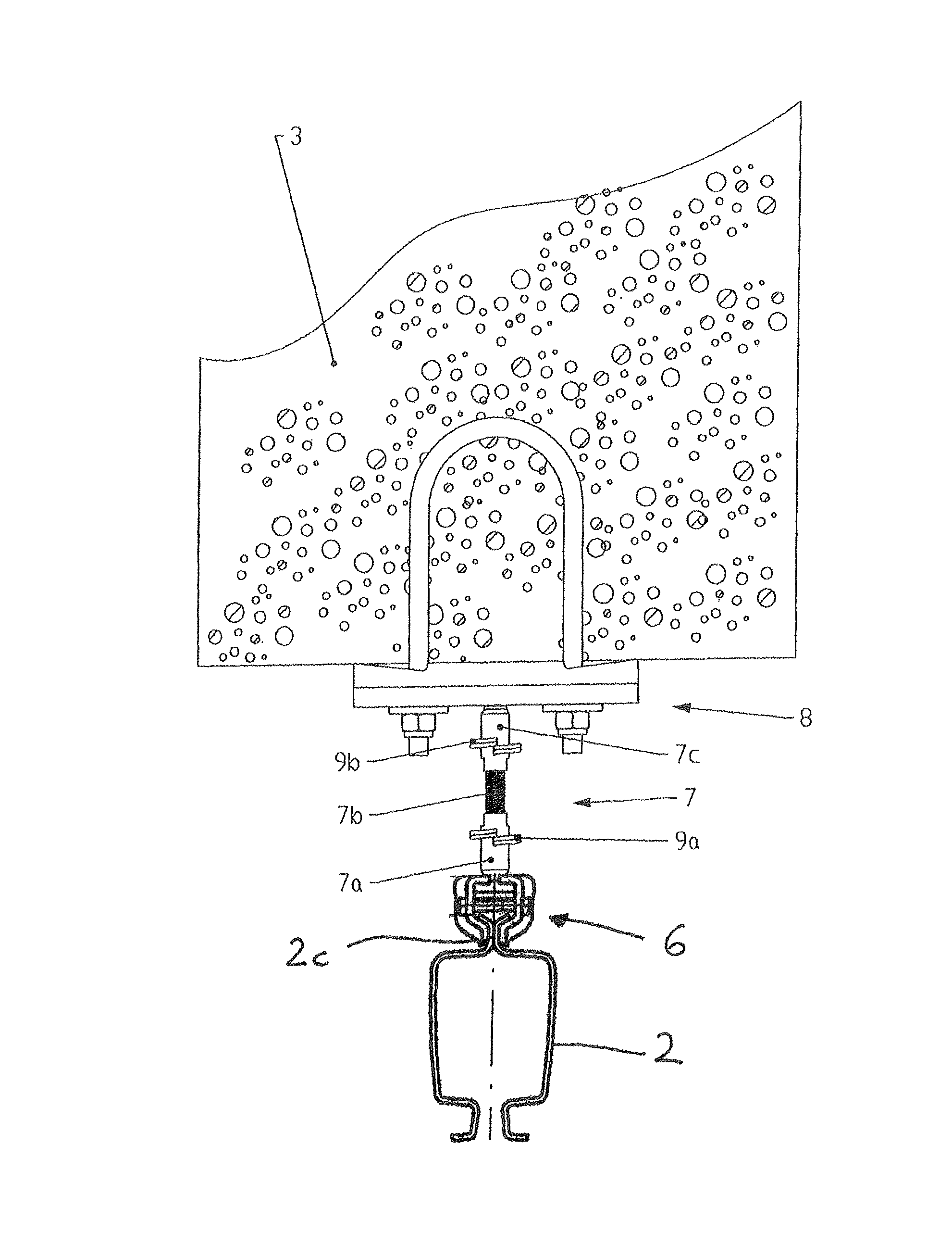
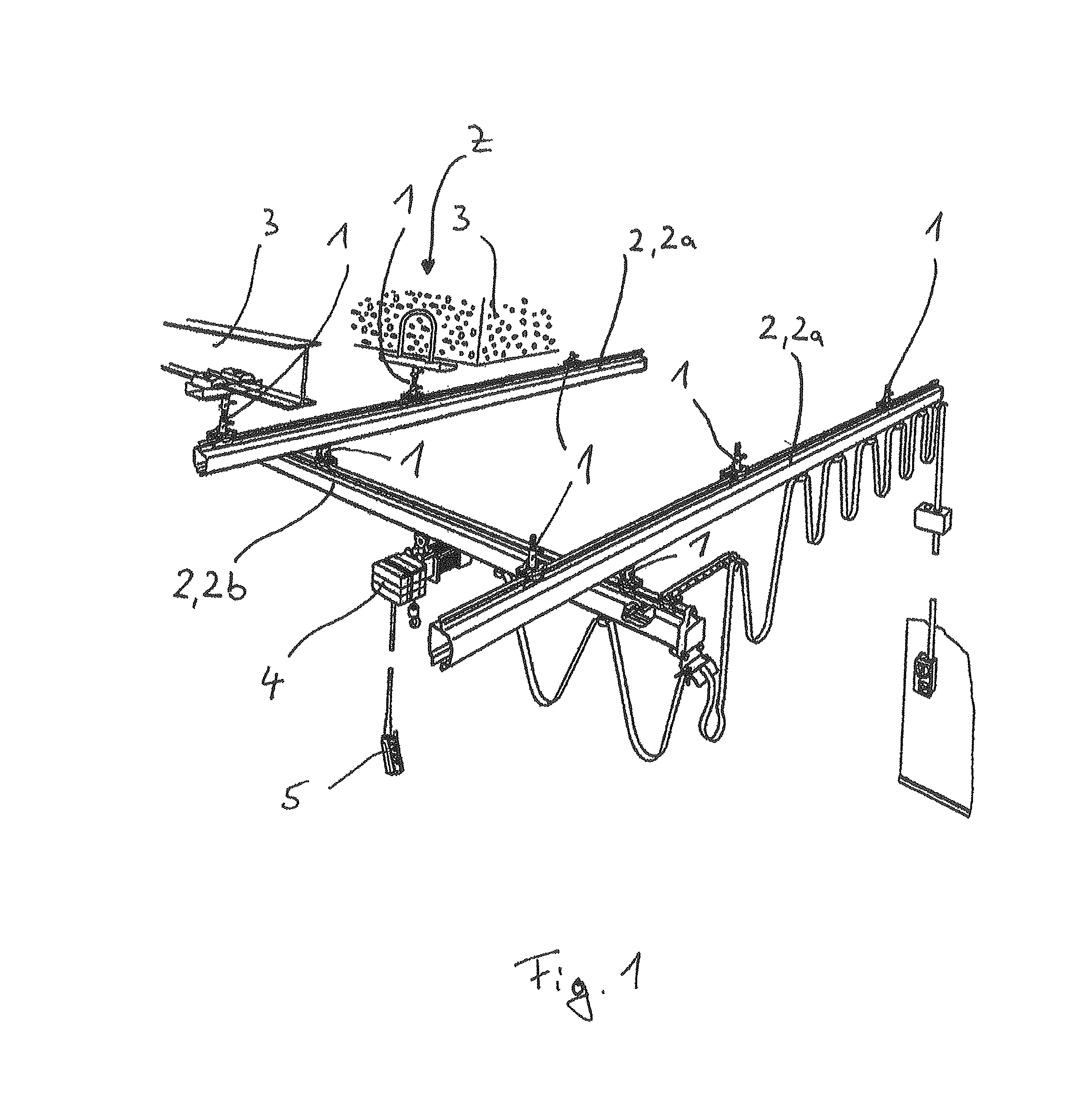
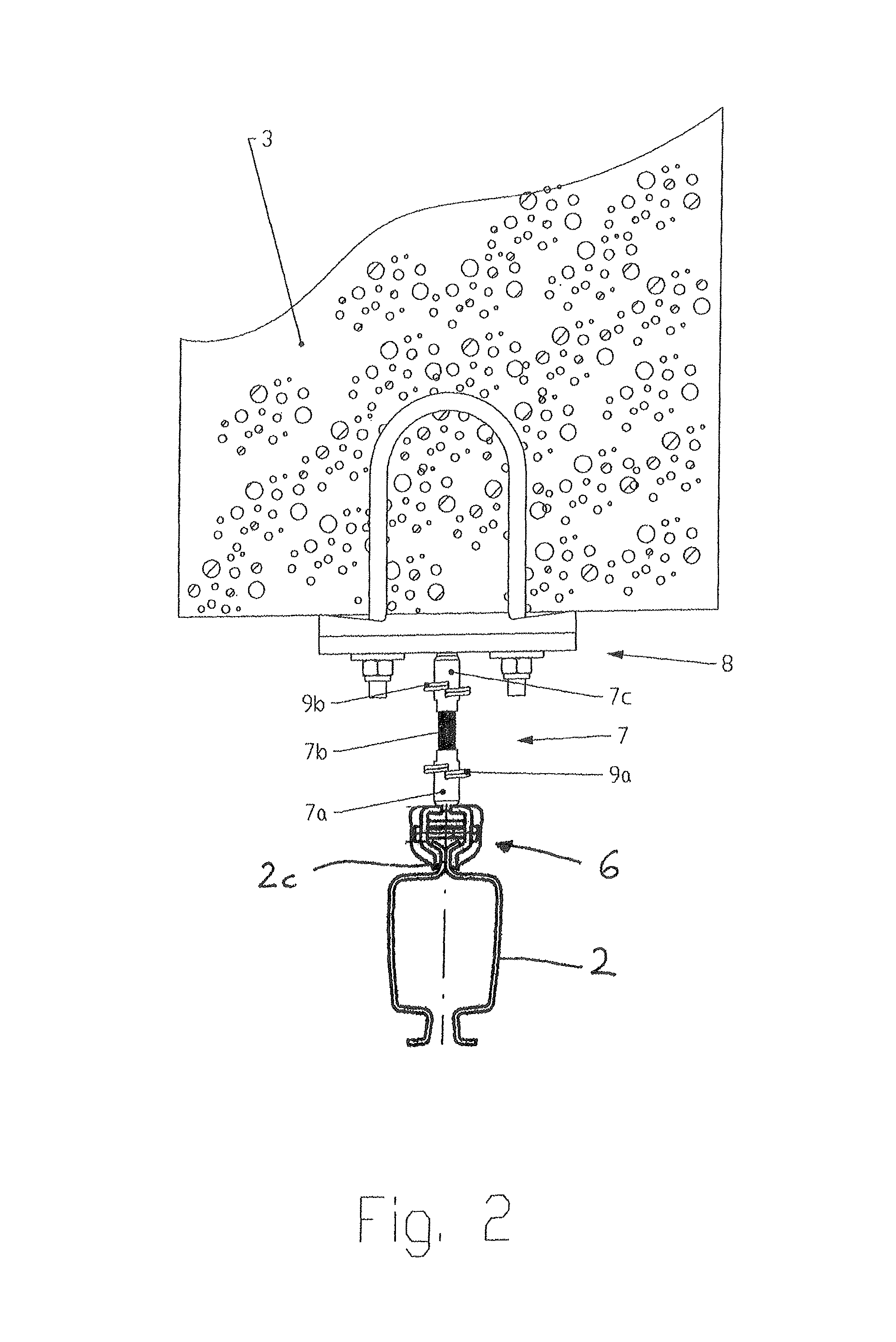
[0023]FIG. 1 shows a plurality of suspension devices 1 in conjunction with a single girder suspension crane. By means of the suspension devices 1, rails 2, which extend substantially horizontally and are profiled in a downwardly open c-shape, are suspended on supporting elements 3 or further rails 2. The supporting elements 3 are formed as I-beams. Since the present exemplified embodiment relates to a single girder suspension crane, two first rails 2a, which extend in a substantially horizontal manner in parallel with and at a spaced disposition with respect to each other, are provided and are used as running rails of the single girder suspension crane, and a second rail 2b, which forms a crane rail, which is oriented substantially transversely with respect to the first rails 2a and can travel along the first rails 2a. For this purpose, the second rail 2b is suspended via two suspension devices 1 in each case on a travelling mechanism which is not shown and can travel along the firs...


PUM


Abstract

A suspending device for a rail, in particular a rail of an overhead conveyor or lifting gear, with a tensile element, which comprises a threaded rod and at least one connecting part that is screwed to the latter, and with a securing element, which secures the screw connection between the threaded rod and the connecting part against loosening. The suspending device for a rail, in particular a running rail of a suspended conveyor or lifting gear, allows simplified and secure mounting in that the securing element engages in a groove with a pin part in the assembled state, with the groove being disposed in the threaded rod.

Description

CROSS REFERENCE TO RELATED APPLICATION[0001]The present application claims the priority benefits of International Patent Application No. PCT / EP2011 / 064242, filed on Aug. 18, 2011, and also of German Patent Application No. DE 10 2010 037 229.3, filed on Aug. 30, 2010, which are hereby incorporated herein by reference in their entireties.BACKGROUND OF THE INVENTION[0002]The invention relates to a suspension device for a rail, in particular a rail of an overhead conveyor or a lifting gear, having a tensile element which includes a threaded rod and at least one connection part screwed thereto, and having a securing element which prevents the screw connection between the threaded rod and the connection part from being loosened.[0003]A suspension for a crane rail on a supporting mechanism in the form of a cover or a cover profile is known from German patent document DE 10 2005 040 421 B4. A crane can travel along the crane rail via travelling mechanisms. The crane rail is attached to the ...

Claims


Application Information

Patent Timeline
Patent Type & Authority Patents(United States)
IPC IPC(8): B65G41/00B66C7/04
CPCB65G41/00B66C7/04E01B3/00
Inventor BHOSALE, SHRIKANTUTTEKAR, MAHESHKHADKE, DEEPTIDESAI, DEEPAKSEAL, AKHOYMULLER, SVEN
Owner KONECRANES GLOBAL
Why Eureka
Try Eureka