Portable cutting machine

a cutting machine and portable technology, applied in the field of portable cutting machines, can solve the problems of increasing the replacement frequency of the foot members, increasing the running cost so as to prevent the unintended movement attenuating the engine vibration, and increasing the running cost of the portable cutting machine

Active Publication Date: 2015-09-29
KOKI HLDG CO LTD
View PDF22 Cites 1 Cited by
  • Summary
  • Abstract
  • Description
  • Claims
  • Application Information

AI Technical Summary

Benefits of technology

[0004]Meanwhile, in order to prevent unintended movement of the portable cutting machine due to engine vibrations when the portable cutting machine is placed on the workpiece to be cut, the foot members to be in contact with the workpiece to be cut are required to have a function of attenuating the engine vibrations. In order to impart such an attenuation function to the foot members, the foot members are generally formed by using a rubber material. However, forming the foot members simply by the rubber material causes increase in the running cost of the portable cutting machine. More specifically, since the foot members slide on a workpiece to be cut such as concrete in a cutting operation, when a rubber material having inferior wear resistance is used, the replacement frequency of the foot members is increased, which has caused increase in the running cost.
[0005]An object of the present invention is to suppress the running cost of a portable cutting machine.
[0007]According to the present invention, the first and second contact members are provided at the lower part of the cutting-machine main body, the first contact member is projecting downward relative to the second contact member, and the second contact member is provided so as to be attachable / detachable to / from the cutting-machine main body. In this manner, when the cutting-machine main body is tilted on the workpiece to be cut in order to cut the workpiece to be cut, the member that is in contact with the workpiece to be cut can be switched from the first contact member to the second contact member. Therefore, damage on the first contact member can be prevented, and the running cost of the portable cutting machine can be suppressed. Moreover, since the second contact member is provided so as to be attachable / detachable to / from the cutting-machine main body, if the second contact member to be in contact with the workpiece to be cut is damaged, only the damaged second contact member can be replaced, and the running cost of the portable cutting machine can be suppressed.

Problems solved by technology

However, forming the foot members simply by the rubber material causes increase in the running cost of the portable cutting machine.
More specifically, since the foot members slide on a workpiece to be cut such as concrete in a cutting operation, when a rubber material having inferior wear resistance is used, the replacement frequency of the foot members is increased, which has caused increase in the running cost.

Method used


Image

  • Portable cutting machine
  • Portable cutting machine
  • Portable cutting machine

Examples


Embodiment Construction

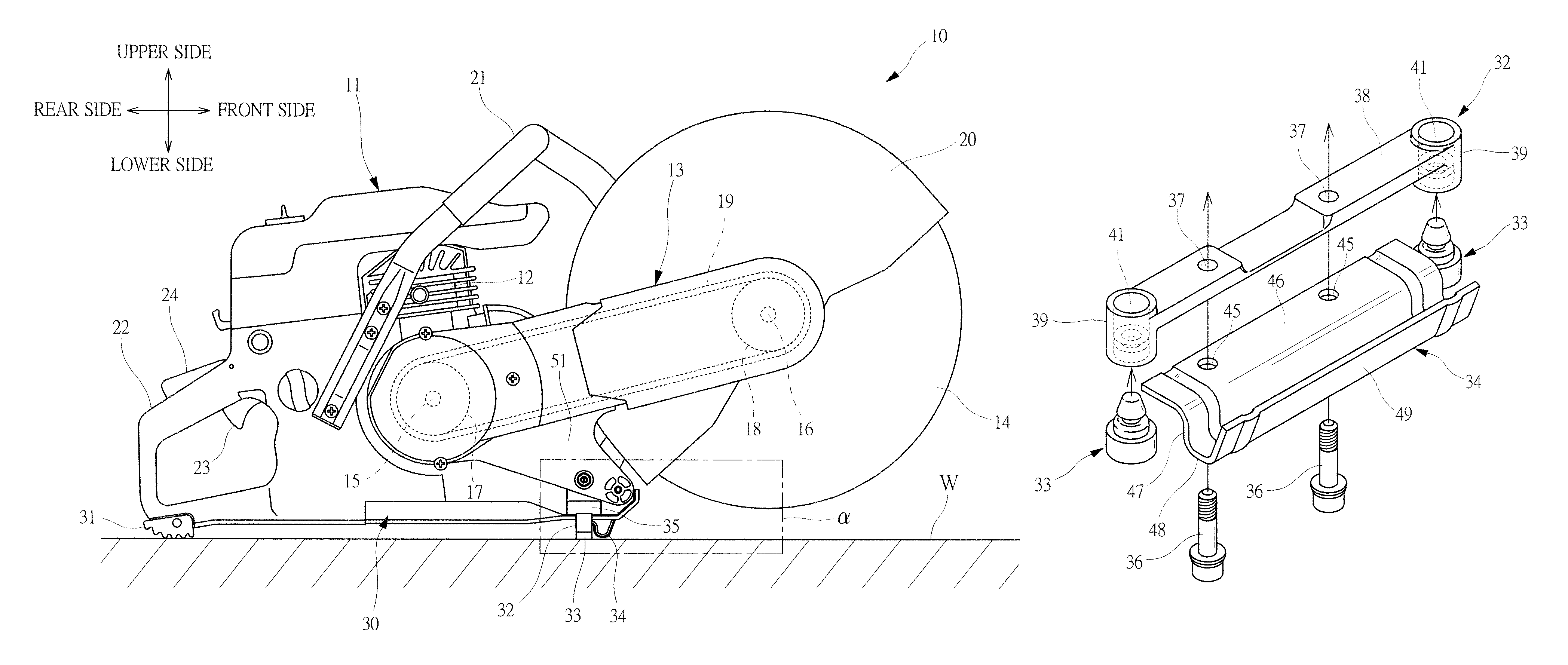
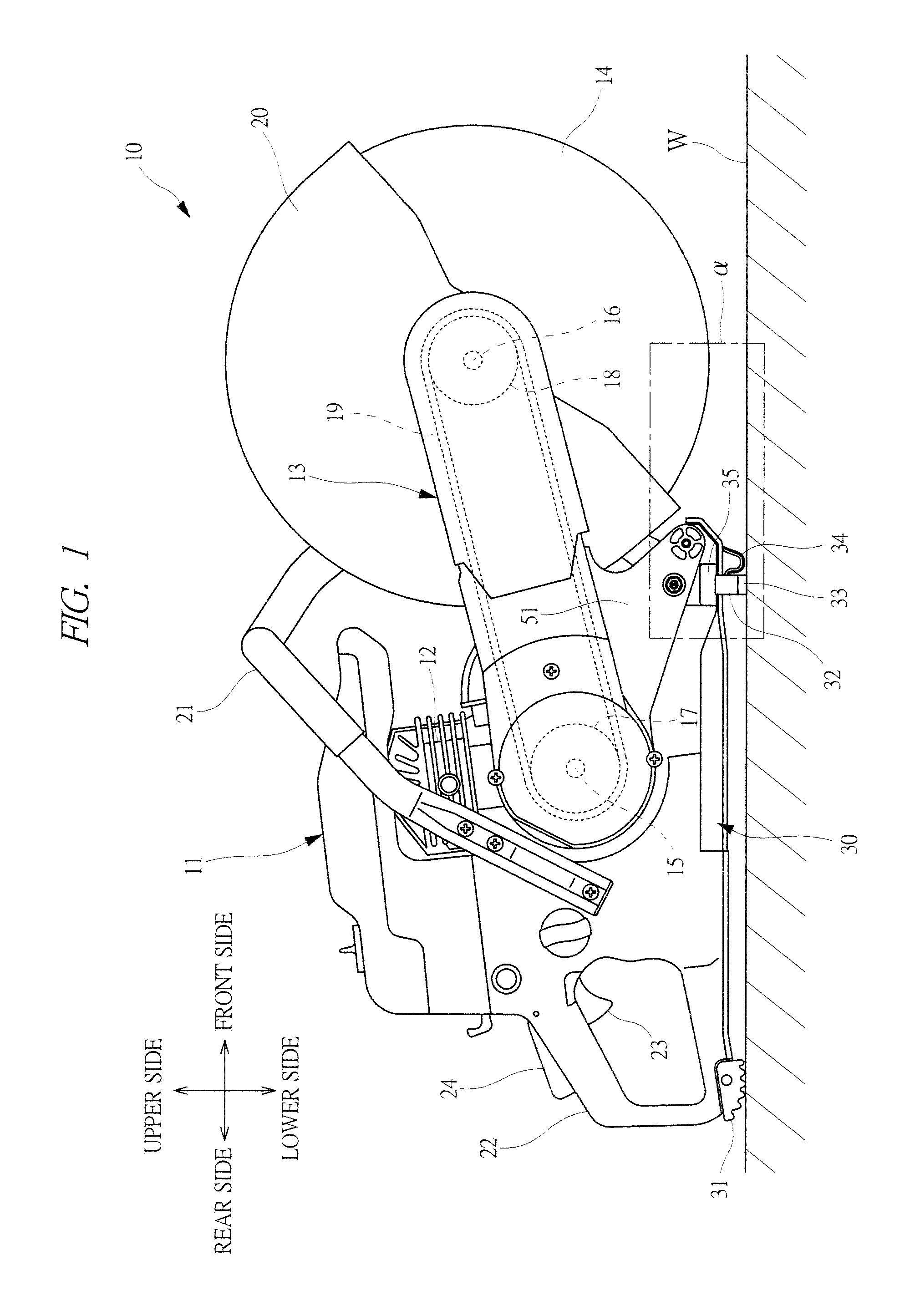
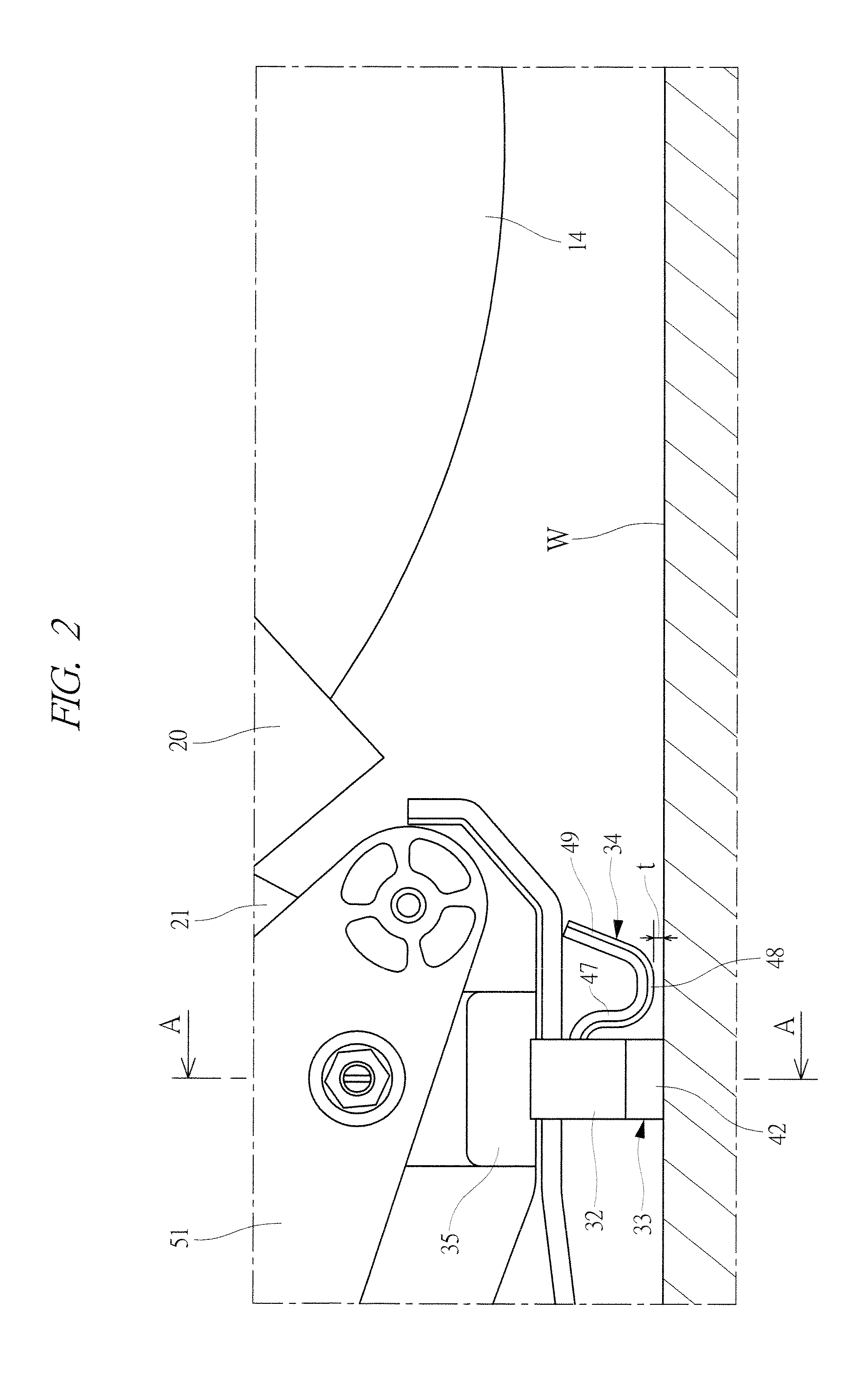
[0026]Hereinafter, an embodiment of the present invention will be described in detail based on drawings. FIG. 1 is a lateral view showing an engine cutter 10 serving as a portable cutting machine according to an embodiment of the present invention. As shown in FIG. 1, the engine cutter 10 has a cutting-machine main body 11, and an engine 12 serving as a drive source is mounted in the cutting-machine main body 11. A power transmitting arm 13 is attached to a crankcase (not shown) of the engine 12, and a disk-like blade 14 is attached to a distal-end part of the power transmitting arm 13. In this manner, the blade 14 is provided at one end side of the cutting-machine main body 11. Also, an output shaft 15 which is coupled to a crankshaft (not shown) via a centrifugal clutch and a rotation shaft 16 which is fixed to a center part of the blade 14 are provided to the power transmitting arm 13. A driving pulley 17 is fixed to the output shaft 15, and a driven pulley 18 is fixed to the rot...


PUM

PropertyMeasurementUnit
elastic modulusaaaaaaaaaa
elasticaaaaaaaaaa
cutting depthaaaaaaaaaa

Abstract

Front feet are provided at a lower part of a cutting-machine main body via a foot holder. Furthermore, a slider positioned on a front side relative to the front feet is provided at the lower part. When a workpiece to be cut is to be cut by a blade, the cutting-machine main body is tilted so as to let the blade go down. When the cutting-machine main body is tilted, a state where the front feet are in contact with the workpiece is switched to a state where the slider is in contact with the workpiece. Then, by moving the cutting-machine main body forward while sliding the slider on the workpiece, the workpiece is cut by the blade. In the cutting operation, the front feet can get away from the workpiece. Therefore, damage of the front feet can be prevented, and the running cost can be suppressed.

Description

CROSS-REFERENCE TO RELATED APPLICATION[0001]The present application claims priority from Japanese Patent Application No. 2012-007769 filed on Jan. 18, 2012, the content of which is hereby incorporated by reference into this application.TECHNICAL FIELD OF THE INVENTION[0002]The present invention relates to a portable cutting machine provided with a blade which is rotary-driven by an engine.BACKGROUND OF THE INVENTION[0003]Portable cutting machines for carrying out marking or cutting operations for concrete, asphalt, stone materials, and others include, for example, an engine cutter. The portable cutting machine also referred to as a hand cutting machine has a cutting-machine main body in which an engine serving as a drive source is mounted, a blade to be rotary-driven by the engine is provided on a front side of the cutting-machine main body, and a rear handle to be gripped by an operator is provided on a rear side of the cutting-machine main body. Furthermore, foot members to be in ...

Claims


Application Information

Patent Timeline
Patent Type & Authority Patents(United States)
IPC IPC(8): B28D1/04B28D1/22B23D45/16B23D47/02
CPCB28D1/228B23D45/16B23D47/02B28D1/045
Inventor YOKOYAMA, YOSHIKAZUKAWAHATA, YASUOKI
Owner KOKI HLDG CO LTD
Why Eureka
Try Eureka