Correlated control for close focus stereoscopic viewing

a correlated control and stereoscopic technology, applied in the field of stereoscopic, can solve the problems of inability to infrared imaging in the medical environment, and inability to easily observe anything that cannot be seen in the visible region of the electromagnetic spectrum such as bone overheating, tissue overheating and the lik

Inactive Publication Date: 2015-09-29
BAE SYST INFORMATION & ELECTRONICS SYST INTERGRATION INC
View PDF3 Cites 0 Cited by
  • Summary
  • Abstract
  • Description
  • Claims
  • Application Information

AI Technical Summary

Benefits of technology

[0018]More particularly, in order to be able to provide exceptionally sharp or crisp thermal imaging for medical applications and the like in which subsurface characteristics are made viewable with sufficient sharpness, an infrared binocular arrangement includes the ability to have the optical center lines of the two optical channels intersect at a point as little as 6 inches from the objective lenses of the binoculars to as much as 60 inches, thus to provide exceptionally sharp close in thermal image viewing. Simultaneous with the adjustment or skewing of the two optical center lines, the focal plane arrays in each of the channels are focused either mechanically or electronically such that not only are the optical center lines of the channels coincident directly at the point to be imaged, but also the focal plane arrays associated with each of the channels are independently adjusted so that exceptional stereo infrared clarity is achieved.
[0024]The results of the two actions provide a clear image of underlying thermal structures such as for instance in phlebotomy the ability to resolve even the thinnest of veins. When used in phlebotomy the subject binocular device is mounted above the arm or leg to be phlebotomized. A 3D display driven by the focal point arrays provides the technician with a clear accurate picture of where the subsurface veins are and the ability to be able to insert a needle at the exact point where the vein occurs. Unlike monocular systems, binocular infrared optics allow depth perception to assure proper placement of surgical instruments.

Problems solved by technology

In the past infrared imaging in the medical environment to detect bleeding and arterial structure and for instance anything that cannot be seen in the visible region of the electromagnetic spectrum such as bone overheating, tissue overheating and the like cannot be readily observed due to the lack of the ability of instruments to provide a reasonably sharp infrared image of the inspected area.
Moreover, focal plane arrays for infrared imaging in the past have only been available with 28 micron pixel spacing which does not lend itself to anything other than a relatively fuzzy picture of the body part being inspected by the thermal imagery process.
However with 28 micron pixel spacing image quality remains poor.
However, those IR imaging systems that were capable of 1 meter focal lengths were not useful in close up viewing of the human body that require a 6 inch to 60 inch operating range.
Thus, short range thermal imaging only resulted in fuzzy or blurry images.
In short, these devices could not focus close in on subjects.
One of the reasons for the failure of IR imagers to have a very short focus was in part due to the size of the optics and the hardware necessary to provide a close in sharp image.
It will be appreciated that providing a blotchy image of a human body part or area is not very useful in detecting subsurface structure.
Depth perception is oftentimes important because when doing surgery one can accidently for instance cut an adjacent structure so that for instance blood vessels could be nicked during the procedure.
Thus in the prior art there were no stereo infrared imaging systems used, much less those capable of imaging targets within about 6 inches of the objective lenses of the binoculars.
However, just simply having the two optical channels having optical center lines which intersect at a distance from the binoculars is not sufficient to provide crisp focusing.
Moreover, any movement of the image focal plane in the two channels of the above-mentioned patent is restricted to adjusting the image focal plane in one channel to be exactly at the same distance as the image focal plane of the other channel, there being no independent adjustment of the focal planes in each channel and certainly no automatic focus involving the movement of focal plane arrays in each of the channels relative to their own objective lenses.

Method used


Image

  • Correlated control for close focus stereoscopic viewing
  • Correlated control for close focus stereoscopic viewing
  • Correlated control for close focus stereoscopic viewing

Examples


Embodiment Construction

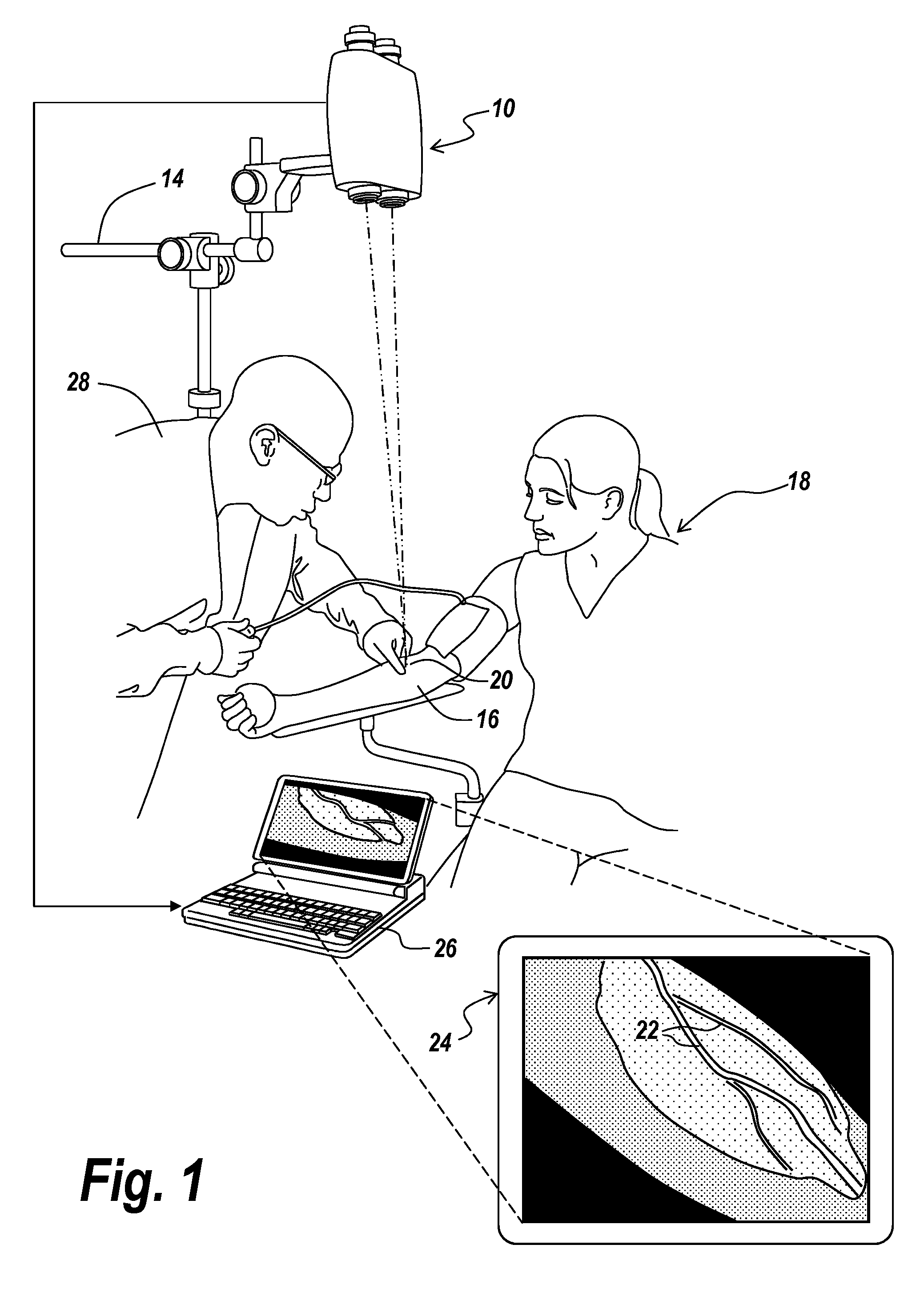
[0036]Referring now to FIG. 1, a binocular infrared imaging system 10 is located by a support apparatus 14 above the arm 16 of a patient 18 so that the point of focus of the binocular is at a point 20 on the arm of the patient.

[0037]The purpose of providing such an infrared imaging device is to be able to locate subsurface structures in the arm in this case for the purpose of a phlebotomy, in which the subsurface structures to be detected are the veins 22 in arm 16 as projected onto a display 24 when using for instance a computer laptop 26 coupled to the focal plane arrays of the binocular device. It will be appreciated that FIG. 1 is for illustrative purposes to show that the image developed by the infrared binocular is exceedingly crisp and sharp. It will be noted that display 24 may be a three dimensional display for providing depth perception. Alternatively individual LCD displays may be mounted in the eyepieces of the binoculars, with the small LCD displays driven by the focal ...


PUM


Abstract

Exceptionally crisp infrared images are provided by a binocular infrared imaging system for close in focusing that simultaneously directs the center lines of the optical channels to a close in point while at the same time providing auto focusing.

Description

STATEMENT OF GOVERNMENT INTEREST[0001]The invention was made with United States Government support under Contract No. H94003-04-D-002 / 0076 awarded by the US Army. The United States Government has certain rights in this invention.RELATED APPLICATIONS[0002]This application claims rights under 35 USC §119(e) from U.S. Application Ser. No. 61 / 674,432 filed Jul. 23, 2012, the contents of which are incorporated herein by reference.FIELD OF THE INVENTION[0003]This invention relates to stereoscopic and more particularly to an infrared system for close in infrared imaging, especially of the human body so that ultra-sharp stereoscopic images of a region on the body may be presented.BACKGROUND OF THE INVENTION[0004]In phlebotomy and other medical procedures it is oftentimes important to be able to see subsurface structures in order to better perform a surgical operation or for instance to locate veins in order to successfully complete a phlebotomy.[0005]In the past infrared imaging in the medi...

Claims


Application Information

Patent Timeline
Patent Type & Authority Patents(United States)
IPC IPC(8): G02B23/00G02B23/18G03B15/14H01L27/146G02B23/12A61B5/00G02B7/06G03B17/48H04N13/04H04N13/02H04N5/33H04N5/225
CPCG03B15/14A61B5/0068A61B5/489G02B7/06G02B23/12G02B23/18G03B17/48H01L27/14625H04N5/2251H04N5/33H04N13/0239H04N13/0402A61B5/15003A61B5/150748H04N13/239H04N13/302H04N23/50
Inventor FRANZINI, JOHNROBICHAUD, MATTHEW
Owner BAE SYST INFORMATION & ELECTRONICS SYST INTERGRATION INC
Why Eureka
Try Eureka