Magnetic toner

a toner and magnetic technology, applied in the field of magnetic toner, can solve the problems of white void formation, image disturbance, and toner layer disturbance, and achieve the effect of excellent transferability and high image density

Active Publication Date: 2015-10-06
CANON KK
View PDF18 Cites 28 Cited by
  • Summary
  • Abstract
  • Description
  • Claims
  • Application Information

AI Technical Summary

Benefits of technology

[0026]The present invention can provide a magnetic toner that, regardless of the environment, gives a high image density and exhibits an excellent transferability.

Problems solved by technology

Considering problems related to the transfer step more closely, transfer defects are an example of image defects that are realized when there are problems during transfer.
At this point, toner may remain on the electrostatic latent image-bearing member without undergoing transfer and the toner layer may undergo disturbances during transfer and defects and nonuniformity on the image may be produced as a result.
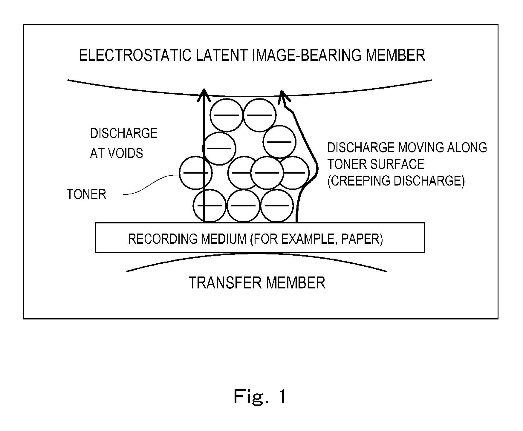
A discharge phenomenon—which can occur between the electrostatic latent image-bearing member and the transfer material due to the large bias being applied between the electrostatic latent image-bearing member and the transfer material—is a cause of transfer defects.
Due to this, the toner remaining on the electrostatic latent image-bearing member increases and the image may be disturbed and white voids may be formed.
However, the effects are inadequate in a high-humidity environment, in which discharge readily occurs.
On the other hand, toners have been disclosed that have sought to solve problems by focusing on the release of external additives (refer to Patent Literatures 3 and 4), but toner transferability again cannot be regarded as adequate in these cases.
However, the actual state of adhesion by external additives is substantially different from the value calculated assuming the toner to be a sphere, and this theoretical coverage ratio has little effect with regard to the transferability in a high-humidity environment, which is the problem identified above, and improvement has thus been required.

Method used


Image

  • Magnetic toner
  • Magnetic toner
  • Magnetic toner

Examples


example 1

The Image-Forming Apparatus

[0286]The image-forming apparatus was an LBP-3100 (Canon, Inc.), which was equipped with a toner carrying member that had a diameter of 10 mm; it was modified by connection to an external power source so that its transfer bias could be modified. Discharge is facilitated by a high transfer bias, enabling rigorous evaluation of the transfer defects. In addition, the transferability is generally severely tasked under a high-humidity environment. Using this modified apparatus and magnetic toner 1, a 1500-sheet image printing test was performed in one-sheet intermittent mode of horizontal lines at a print percentage of 2% in a high-temperature, high-humidity environment (32.5° C. / 80% RH) at an ordinary transfer bias (0.5 kV). After the 1500 sheets had been printed, a single print of a solid black image was output. The transfer bias was subsequently set to 1.5 kV and a solid black image was output.

[0287]On the other hand, using this modified apparatus and magnet...

examples 2 to 46

[0294]Image output testing was performed as in Example 1, but using magnetic toners 2 to 46. According to the results, all of the magnetic toners provided images at at least practically unproblematic levels in pre- and post-durability testing. The results of the evaluations are shown in Table 5.


PUM

PropertyMeasurementUnit
temperatureaaaaaaaaaa
frequencyaaaaaaaaaa
volume-average particle diameteraaaaaaaaaa

Abstract

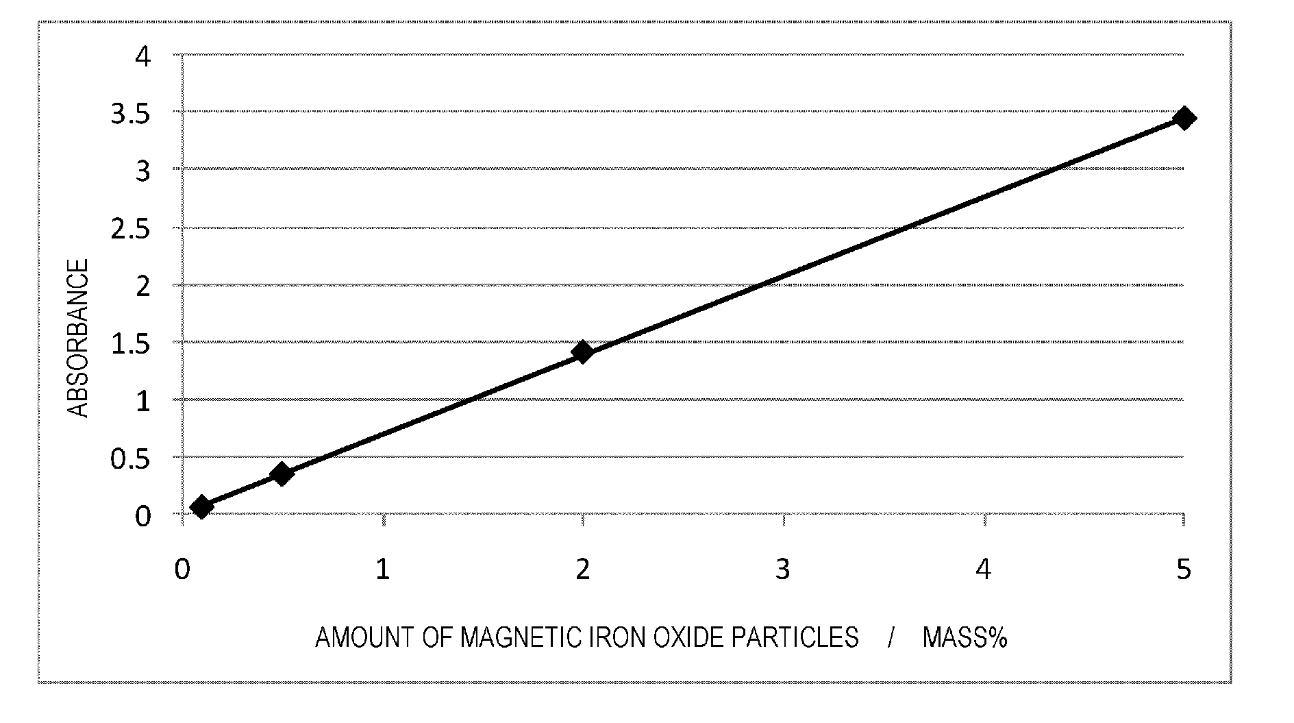
A magnetic toner includes: magnetic toner particles containing a binder resin and a magnetic body; and inorganic fine particles that are present on the surface of the magnetic toner particles and are not a magnetic iron oxide and magnetic iron oxide particles that are present on the surface of the magnetic toner particles, wherein the inorganic fine particles present on the surface of the magnetic toner particles contain metal oxide fine particles, the metal oxide fine particles containing silica fine particles, and optionally containing titania fine particles and alumina fine particles, and a content of the silica fine particles being at least 85 mass % with respect to a total mass of the silica fine particles, the titania fine particles and the alumina fine particles; when a coverage ratio A (%) is a coverage ratio of the magnetic toner particles' surface by the inorganic fine particles and a coverage ratio B (%) is a coverage ratio of the magnetic toner particles' surface by the inorganic fine particles that are fixed to the magnetic toner particles' surface, the coverage ratio A and B / A satisfy prescribed ranges; and the magnetic iron oxide particles present on the magnetic toner particles' surface are from at least 0.10 mass % to not more than 5.00 mass % with respect to the total amount of the magnetic toner.

Description

TECHNICAL FIELD[0001]The present invention relates to a magnetic toner for use in recording methods that use, for example, electrophotographic methods.BACKGROUND ART[0002]Numerous methods are known for the execution of electrophotography. At a general level, using a photoconductive material an electrostatic latent image is formed on an electrostatic latent image-bearing member (also referred to as a “photosensitive member” below) by various means. Then, a visible image is made by developing this electrostatic latent image with toner; as necessary the toner image is transferred to a recording medium such as paper; and a copied article is obtained by fixing the toner image on the recording medium by, for example, the application of heat or pressure. For example, copiers and printers are image-forming apparatuses that use such an electrophotographic procedure.[0003]Previously, these printers and copiers were connected in networks and such printers were often tasked with printing from a...

Claims


Application Information

Patent Timeline
Patent Type & Authority Patents(United States)
IPC IPC(8): G03G9/083G03G9/097
CPCG03G9/0833G03G9/0836G03G9/0837G03G9/0839G03G9/09708G03G9/09725
Inventor SANO, TOMOHISAMAGOME, MICHIHISAHASEGAWA, YUSUKEOHMORI, ATSUHIKO
Owner CANON KK
Why Eureka
Try Eureka