Cooling of an electric machine

a technology of electric machines and cooling chambers, which is applied in the direction of magnetic circuit rotating parts, lighting and heating apparatus, magnetic circuit shape/form/construction, etc., can solve the problems of increasing the importance of cooling, the inability to work in other working environments, and the large size and bulk of electric machines such as electric motors

Active Publication Date: 2015-10-06
ABB (SCHWEIZ) AG
View PDF26 Cites 3 Cited by
  • Summary
  • Abstract
  • Description
  • Claims
  • Application Information

AI Technical Summary

Benefits of technology

[0021]The present invention has a number of advantages. The thermosyphon heat exchange is performed using the heat exchange unit, which can be small and compact and thus easy to place in an electric machine. The type of cooling performed allows the cooling of a clean first fluid in the chamber using a possibly dirty second fluid, which may be an ambient fluid like air. The separation of fluid streams allows the use of a low pressure drop and a small volume. This also provides the heat exchanger design with scalability since efficiency does not depend on size. The two-phase working fluid inside the heat exchanging unit transports the heat through the heat exchanging unit by natural convection.

Problems solved by technology

Electric machines, such as electric motors, can be large and bulky.
The larger they get and the more energy they generate or draw the issue of cooling gets increasingly important.
This is very convenient in marine applications for example where water is readily available, but might be not possible in some other working environments or when water close to electrical components must be avoided.
In this document the heat exchanging elements used are however bulky.

Method used


Image

  • Cooling of an electric machine
  • Cooling of an electric machine
  • Cooling of an electric machine

Examples


first embodiment

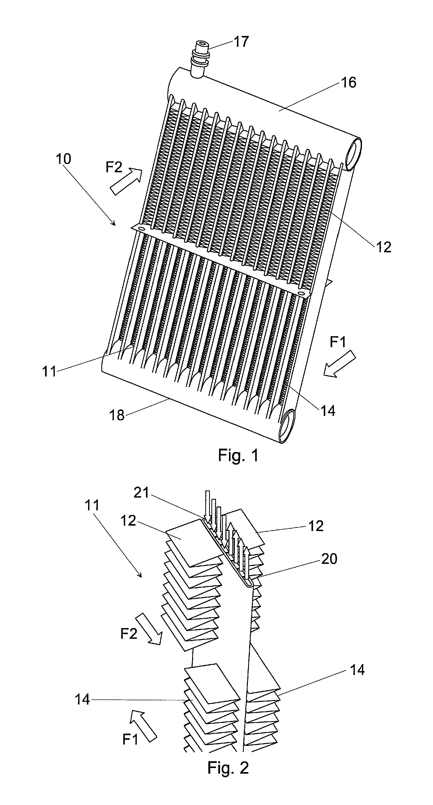
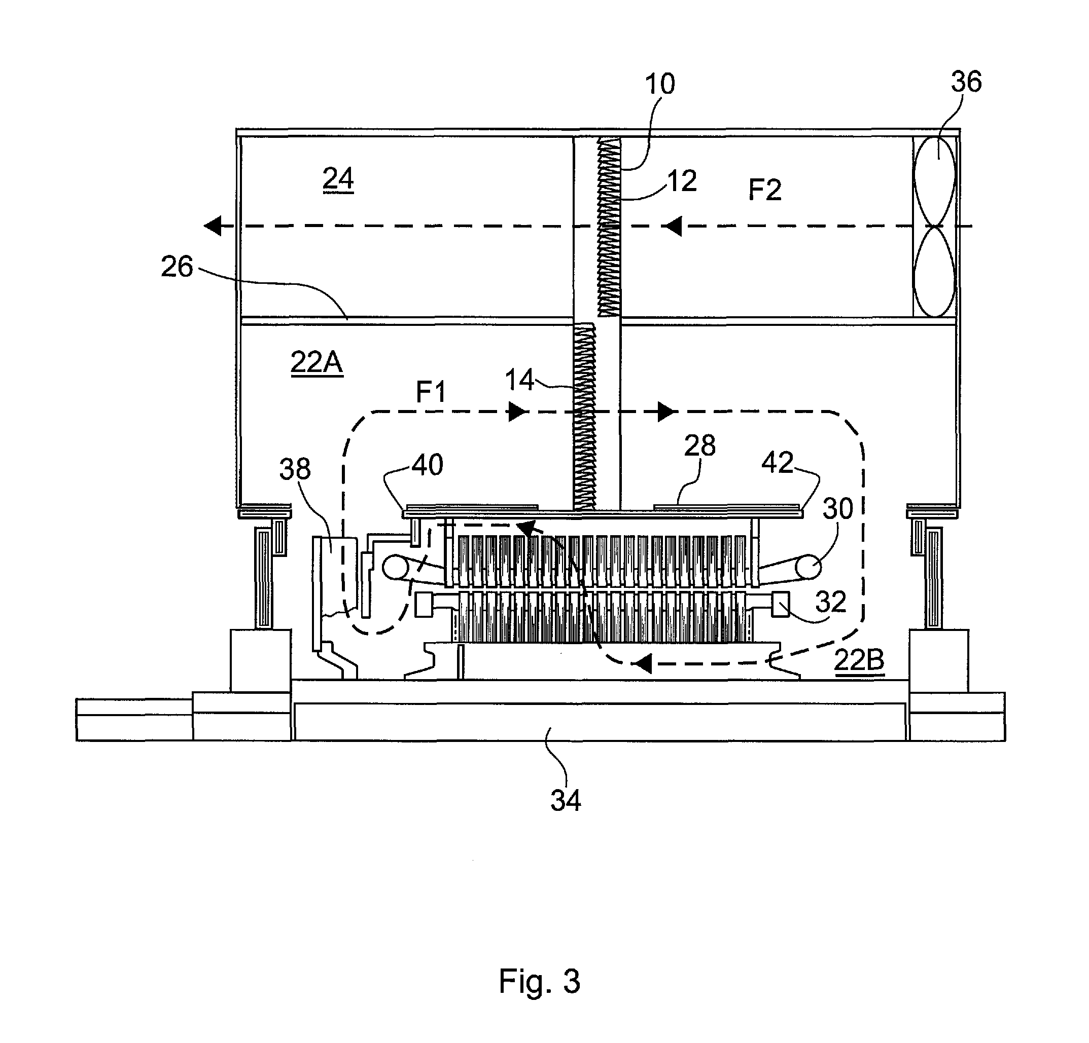
[0039]A sectional view of such an electric machine with heat exchanging unit according to the invention is schematically shown in FIG. 3.

[0040]The electric machine here includes a closed chamber 22 in which the stator 30 and the rotor 32 are provided. The chamber is here furthermore a high Ingress Protection index enclosure. In this first embodiment of the invention the chamber is also made up of a first and a second section 22A and 22B being separated by a partition 28. The partition 28 is here provided with a first opening 40 and with a second opening 42 in order to let the sections communicate with each other. These openings are vertically separated from each other. A part of the heat exchanging unit 10, in this embodiment the lower half, is provided in the first section 22A between the first and second openings, while the stator and rotor 30 and 32 are provided in the second section 22B. The first section 22A is therefore also a cooling section and the second section, in which o...

second embodiment

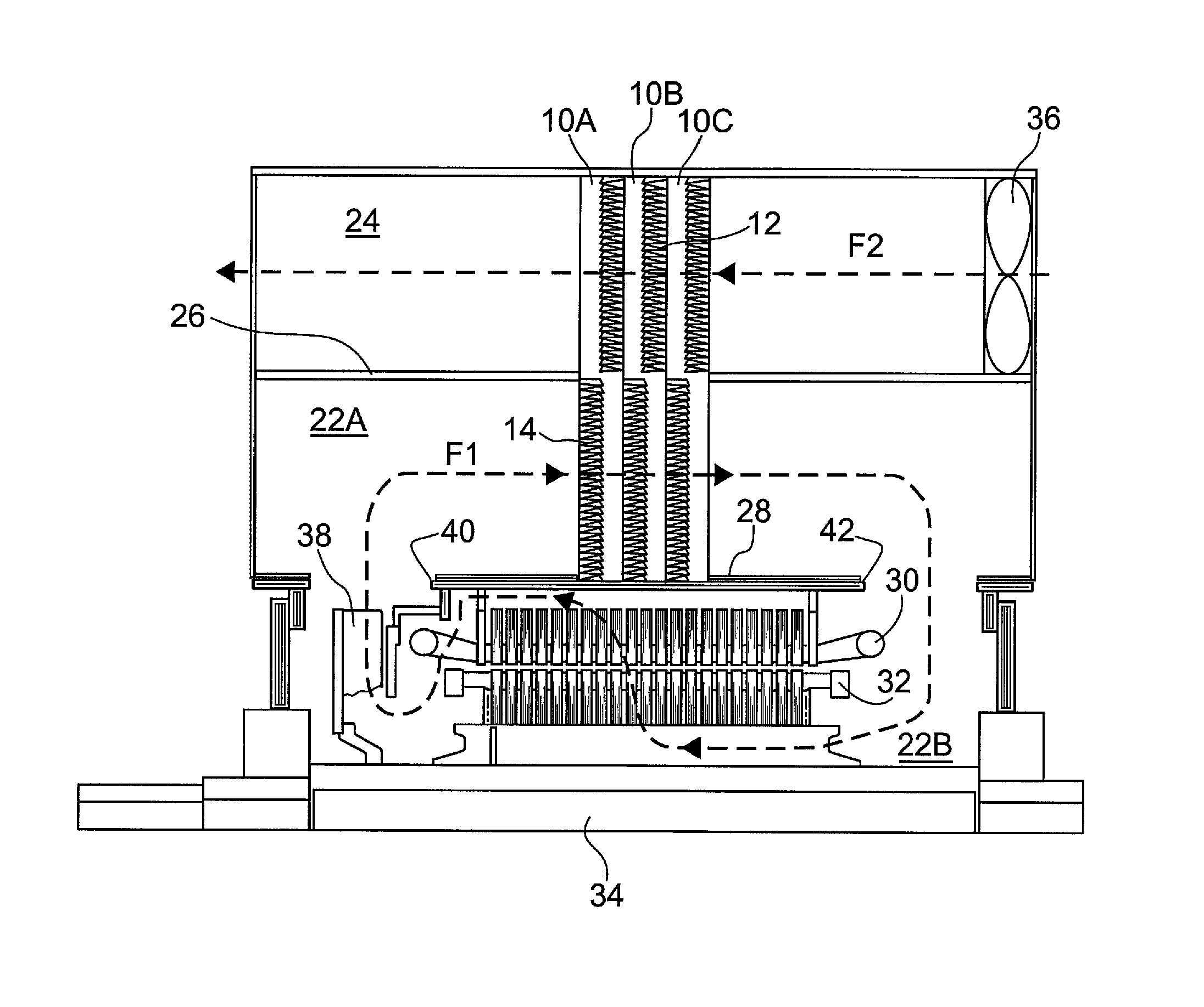
[0052]In the invention this modular realization of the heat exchanging unit is used further.

[0053]This is exemplified in FIG. 4, which shows a sectional view through an electric machine that is similar to the machine in FIG. 3. The only difference here is the heat exchanging unit. In this case the heat exchanging unit is made up of a number of heat exchanging modules 10A, 10B, 10C, each module provided in the same way as the heat exchanging unit described in relation to FIGS. 1 and 2. These modules 10A, 10B, 10C are here stacked after each other in the first section 22A of the chamber, i.e. in a direction from the first opening 40 towards the second opening 42 of the partition 28. This also means that they are placed after each other in the direction of flow of the first fluid F1 in the first section 22A of the chamber. Each module furthermore has the same orientation as the heat exchanging unit of the first embodiment. Also here there is furthermore a single opening in the wall 26 ...

third embodiment

[0057]FIG. 5 shows a sectional view through a part of an electric machine according to the invention where symmetric cooling is used.

[0058]In case of symmetric cooling according to this third embodiment there is, in addition to a first heat exchanging unit 10, also a second heat exchanging unit 44. Furthermore apart from the first opening (not shown) and second opening 42, there is here a third opening 48 in the partition. In this embodiment the first opening is provided centrally in the partition and the first fan (not shown) placed for forcing the first fluid F1 into the first section 22A of the chamber via this first opening. Here the stator and rotor may be placed around this opening. The second and third opening 42 and 48 are then placed peripherally in the chamber and here on opposite sides of the first opening. The first heat exchanging unit 10 is then placed and fixed to the partition between the first opening and the second opening 42 in the first section 22A of the chamber...


PUM


Abstract

An electric machine including a closed chamber with a wall and enclosing a stator, a rotor and a first fluid and a heat exchanging unit stretching from the chamber through the wall to a fluid transporting passage. The heat exchanging unit includes conduits provided in a loop, containing a working fluid and equipped with evaporator channels and condenser channels, first heat transfer elements inside the chamber for transferring heat from the first fluid to the working fluid via the evaporator channels and second heat transfer elements in the passage for transferring heat out of the working fluid via the condenser channels to a second fluid, a first fluid propagating unit inside the chamber forcing the first fluid to circulate and a second fluid propagating unit in the passage forcing the second fluid to flow past the second heat transfer element.

Description

FIELD OF THE INVENTION[0001]The present invention generally relates to electric machines. More particularly the present invention relates to the cooling of such electric machines.BACKGROUND OF THE INVENTION[0002]Electric machines, such as electric motors, can be large and bulky. The larger they get and the more energy they generate or draw the issue of cooling gets increasingly important.[0003]High Ingress Protection index electrical motors do for instance often use a water to air heat exchanger to cool the air inside an enclosure containing the motor. This is very convenient in marine applications for example where water is readily available, but might be not possible in some other working environments or when water close to electrical components must be avoided.[0004]It is also known to use air-to-air heat exchangers in motors. One example on this is given in U.S. Pat. No. 5,844,333, where motor air is cooled through passing coolant tubes with ambient air.[0005]Another type of hea...

Claims


Application Information

Patent Timeline
Patent Type & Authority Patents(United States)
IPC IPC(8): H02K9/18H02K9/19H02K9/06H02K9/12H02K9/14F28D15/02
CPCH02K9/18H02K9/06H02K9/12H02K9/14H02K9/19F28D15/0233F28D15/0266F28D15/0275H02K9/20
Inventor AGOSTINI, BRUNOPINTO, CAJETANMECKEL, CHRISTIANHABERT, MATHIEU
Owner ABB (SCHWEIZ) AG
Why Eureka
Try Eureka