Vehicle and method for operating a vehicle

a technology for vehicles and vehicles, applied in the field of vehicles of a type, can solve the problems of adversely affecting inability to use or recover energy to be expended for the braking of the vehicle, and inability to power the hydraulic consumption devices connected with the internal combustion engine, so as to avoid any impairment in the functioning of the drive unit, increase the transmission ratio of the gear unit, and increase the driving torque made available through the drive unit

Active Publication Date: 2015-10-13
ZF FRIEDRICHSHAFEN AG
View PDF18 Cites 25 Cited by
  • Summary
  • Abstract
  • Description
  • Claims
  • Application Information

AI Technical Summary

Benefits of technology

[0015]Thus, there is a possibility of, in a simple manner, implementing a deceleration of a vehicle, preferably by the driver or by a driving program, for example during a change in driving direction or when the vehicle is traveling downhill, initially by means of an overrun mode of the drive unit, and, upon reaching impermissibly high rotational speeds of the drive unit, automatically supporting deceleration of the vehicle by corresponding actuation of the braking device through the additional actuating device, and thus avoiding any impairment in the functioning of the drive unit in a constructively easy manner.
[0017]If the power request element and / or the driving direction selection element and the brake actuation element are operatively connected through a control unit with a valve device formed as a proportional valve, through which the braking device may be subjected to hydraulic pressure for the representation of a braking torque, the braking device may be automatically actuated during a deceleration process of a vehicle with a low degree of steering and control effort and in a constructively easy manner, in order to avoid damage to the drive unit.
[0018]With one embodiment of the vehicle under the invention, which is likewise characterized by a low degree of actuation effort, a switch valve device is provided, through which the braking device may be subjected to hydraulic pressure either from the valve block or from the valve device.
[0021]In accordance with the invention, when a defined threshold of rotational speed of the drive unit is exceeded, the braking device is operated to an extent that initiates a braking torque in the drive train, in order to avoid any impairment in the functioning of the drive unit in an easy manner.
[0022]With an advantageous variation of the method under the invention, a transmission ratio of the gear unit is increased upon the presence of a specification for the deceleration of the vehicle desired by the driver, by which the driving torque made available through the drive unit is increased in a simple manner.

Problems solved by technology

However, it is disadvantageous that, based on the decoupling of the internal combustion engine from the main gearbox, thus from the output of the vehicle, the energy to be expended for the braking of the vehicle is not usable or recoverable for powering the hydraulic consumption devices connected with the internal combustion engine.
However, it is problematic with this approach that, upon a deceleration process of a vehicle with the starting point of a high speed of the vehicle, the braking action of the drive unit for the implementation of the requested deceleration of the vehicle is able to be realized only if a rotational speed of the drive unit, during the deceleration process of the vehicle, assumes values that adversely affect the functioning of the drive unit under certain circumstances.

Method used


Image

  • Vehicle and method for operating a vehicle
  • Vehicle and method for operating a vehicle

Examples


Embodiment Construction

[0026]Reference will now be made to embodiments of the invention, one or more examples of which are shown in the drawings. Each embodiment is provided by way of explanation of the invention, and not as a limitation of the invention. For example features illustrated or described as part of one embodiment can be combined with another embodiment to yield still another embodiment. It is intended that the present invention include these and other modifications and variations to the embodiments described herein.

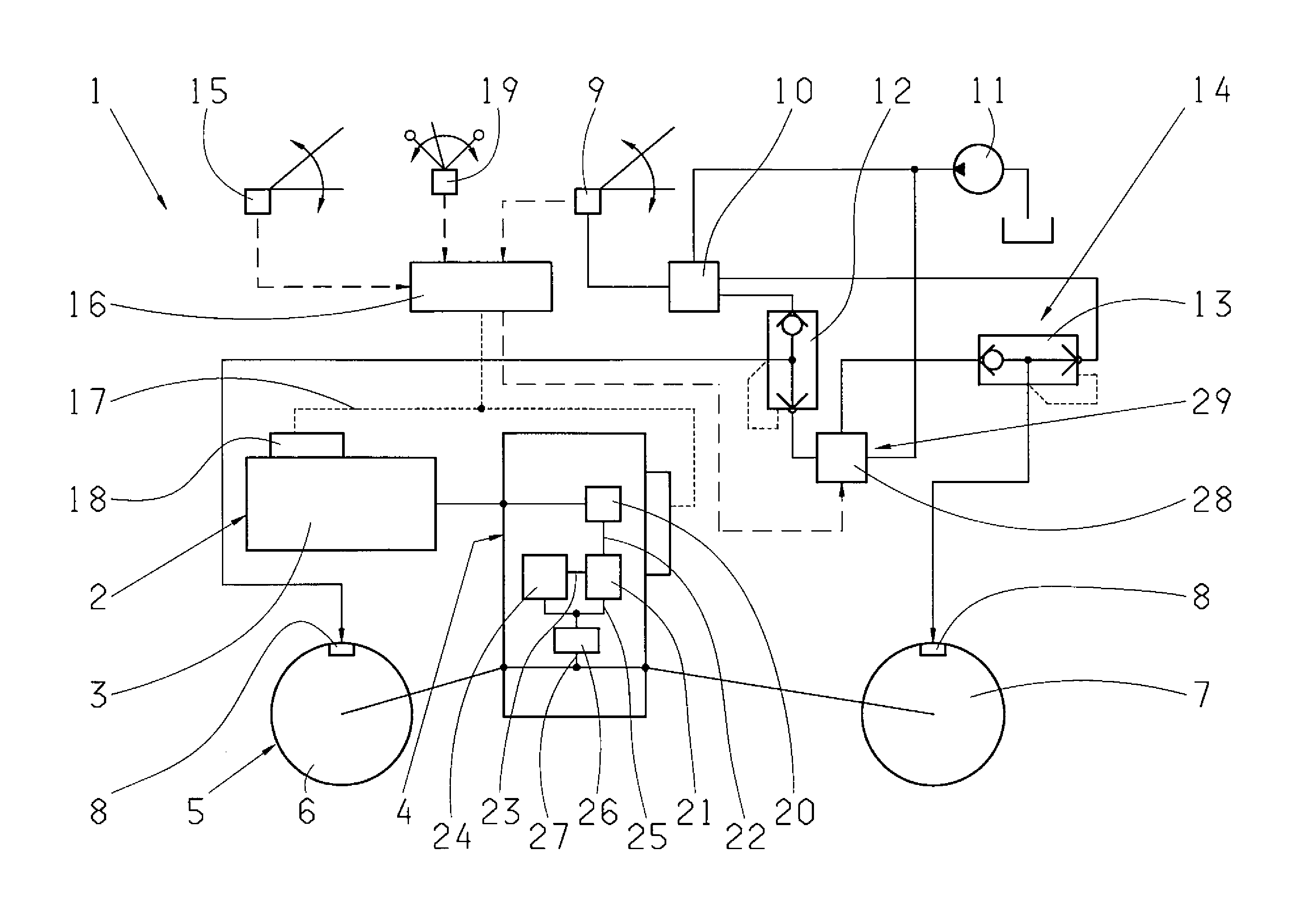
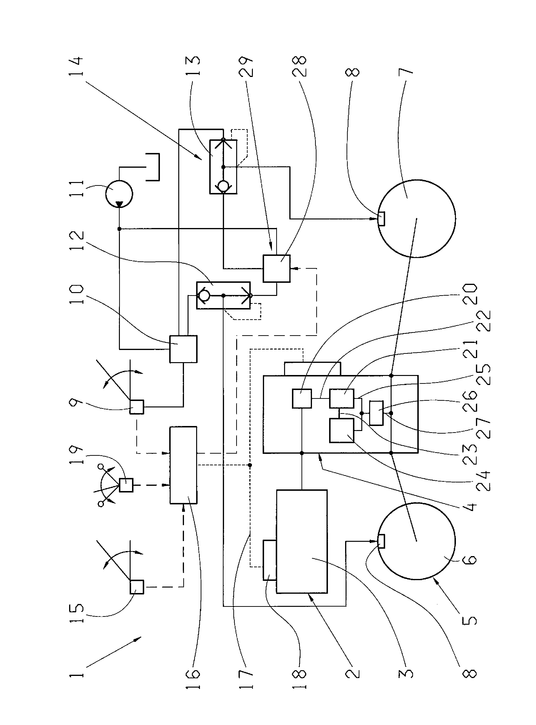
[0027]FIG. 1 presents a functional diagram of a vehicle 1 with a drive train 2, which in this case comprises a drive unit 3 constructed as, for example, a diesel motor, a hydrostatic-mechanical power-split gear unit 4 that is operatively connected to the drive unit 3, an output 5, and / or a front axle 6 and a rear axle 7. The front axle 6 and the rear axle 7 are each allocated to a braking device 8, which in this case features a driving brake with two independent braking circuits.

[0...


PUM


Abstract

A vehicle has a drive train comprising a drive unit, a hydrostatic-mechanical power-split gear unit operatively connected to the drive unit and an output, and at least one braking device. An additional actuating device is allocated to the braking device and is operatively connected with a power request element and / or a driving direction selection element. Upon the presence of a deceleration of the vehicle requested by the driver through the power request element and / or the driving direction selection element and, the braking device is actuated to an extent that initiates a braking torque in the drive train. Upon the presence of a requested deceleration of the vehicle, a driving torque on the side of the drive unit is provided in the area of the output for a braking device that is not actuated by the driver. If the rotational speed of the drive unit exceeds a defined threshold of rotational speed, the braking device is operated to an extent that initiates a braking torque in the drive train.

Description

FIELD OF THE INVENTION[0001]The invention relates to a vehicle of a type with a drive train comprising a drive unit, a hydrostatic-mechanical power-split gear unit that is operatively connected with it and an output, and with at least one braking device, by means of which, upon a corresponding actuation by the driver of a brake actuation element, a braking torque is able to be initiated in the drive train. A driving torque of the drive unit is variable depending on an actuation by the driver of a power request element and a driving direction selection element. The invention also relates to a method for operating such a vehicle.BACKGROUND[0002]DE 602 12 384 T2 discloses a method for operating a vehicle and / or a method for reversing the driving direction of a moving vehicle, for which a movement of a gear selection device is captured in a position that indicates a new intended driving direction. Such a method for reversing driving direction is often carried out during the operating of...

Claims


Application Information

Patent Timeline
Patent Type & Authority Patents(United States)
IPC IPC(8): B60T7/12F16H61/40B60W10/00B60W10/196B60T7/08B60T13/66B60W10/103B60W10/188B60W30/18B60W10/04B60W10/11F16H59/08
CPCB60W10/196B60T7/12B60T13/662B60W10/04B60W10/103B60W10/11B60W10/188B60W30/18045B60W30/18072B60W30/18136B60T7/085Y10T477/644B60W2510/0638B60W2540/10B60W2540/12B60W2540/16B60Y2200/415F16H2059/088Y02T10/60
Inventor LEGNER, JURGEN
Owner ZF FRIEDRICHSHAFEN AG
Why Eureka
Try Eureka