Laser machining apparatus and method for forming a surface on an unifinished product

a technology of laser machining and unfinished products, which is applied in the direction of metal-working equipment, welding equipment, manufacturing tools, etc., can solve the problems of material ablation in the pulse area, and achieve the effect of optimal ablation ra

Active Publication Date: 2011-04-28
FRITZ STUDER AG
View PDF6 Cites 9 Cited by
  • Summary
  • Abstract
  • Description
  • Claims
  • Application Information

AI Technical Summary

Benefits of technology

[0019]The material parts of the unfinished object which cover the surface area to be generated and which have to be ablated are removed preferably in layers which extend essentially parallel to the pulse surface area. The thickness of the ablation layer-in the radiation direction of the laser impulses depends on the impulse frequency of the laser and the relative speed of the pulse area with respect to the unfinished object. Layer thicknesses of several hundredths of a millimeter can be achieved. The ablation layers extend transverse ahead of the area to be formed. The unfinished object can be formed for example into a cutting tool with at least one cutting edge. To this end, the unfinished object includes preferably a cutting material layer or a cutting material element which is arranged on a carrier layer or a carrier element. The material part to be ablated extends over both layers. The positioning arrangement can adjust a first inclination angle for the ablation of the material of the cutting material layer and a second inclination angle for the ablation of the material of the carrier layer. In this way optimal ablation rates can be provided depending on the material to be ablated and, after the ablation of each ablation layer the focus position of the laser beam impulse can be adjusted by the focusing lens or the focusing arrangement.
[0020]It is also possible to determine additional operating parameters depending on the particular material. For example, the intensity of the laser impulse during ablation of the material of the cutting material layer may be different from the intensity during the ablation of the material of the carrier layer. In this way deviations between the desired course of the cutting edge or the area to be formed may be reduced.

Problems solved by technology

This results in a material ablation in the pulse area which is moved relative to the unfinished object like a tool.

Method used


Image

  • Laser machining apparatus and method for forming a surface on an unifinished product
  • Laser machining apparatus and method for forming a surface on an unifinished product
  • Laser machining apparatus and method for forming a surface on an unifinished product

Examples


Embodiment Construction

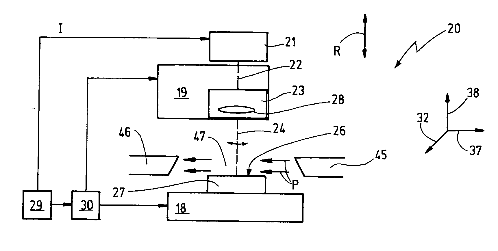
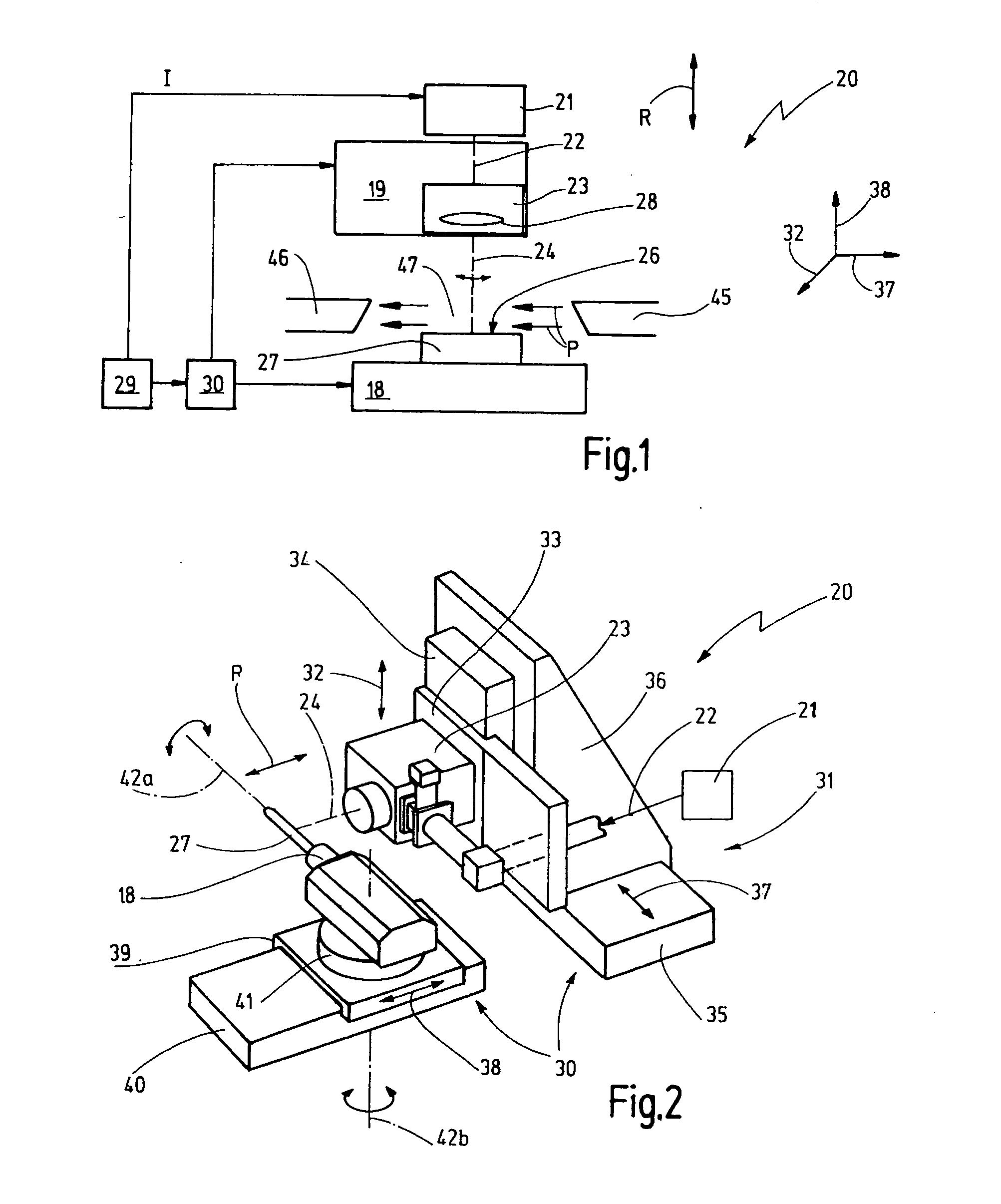
[0032]FIG. 1 shows schematically a laser machining arrangement 20. The laser machining arrangement 20 includes a pulsed laser 21 which generates a pulsed laser beam 22 and directs it to a laser head 19 with a re-directing arrangement 23. The redirecting arrangement 23 can change the orientation of the laser beam impulses 24 and direct the laser beam pulse 24 onto a predetermined impact area 25 of a surface 26 of an unfinished object 27. The redirecting arrangement 23 may also be called a scanner arrangement. It includes also a focusing optical system 28. The unfinished object 27 is disposed in an accommodation area 47.

[0033]The laser machining arrangement 20 also includes a control unit 29 which controls a positioning arrangement 30 by which a relative position between the laser head 19 and the unfinished object can be adjusted and changed. The number of linear axes and axes of rotation of the positioning arrangement 30 may vary. In the preferred embodiment, the positioning arrangem...


PUM

PropertyMeasurementUnit
inclination angleaaaaaaaaaa
frequencyaaaaaaaaaa

Abstract

The invention concerns a method and an apparatus for the laser machining of an unfinished object (27). The unfinished object (27) is to be formed into a cutting tool with a cutting edge (60) and a free surface (62). A laser is provided which generates laser beam impulses (24) which are directed by a redirecting arrangement (23) onto a surface (26) of the unfinished object (27). A laser beam impulse (24) reaches at an impact location the surface (26) of the unfinished object (27) under an inclination angle between the laser beam direction (R) of the laser beam impulse (24) and the surface (62) to be formed on the unfinished object (27). The redirecting arrangement (23) is controlled in such a way that the laser beam impulses (24) impact at adjacent impact locations on form and form a pulse zone (55). With the positioning arrangement a relative movement between the pulse zone (55) and the unfinished object of predetermined speed is established so that the pulse zone (55) formed by the impact locations moves along the surface (26) of the unfinished object (27) and an ablation layer of a layer thickness (dS) is removed with each contour pass.

Description

CROSS-REFERENCE TO RELATED APPLICATION[0001]This application claims the priority benefits of German Application No. 10 2009 044 316.9-34 filed Oct. 22, 2009.BACKGROUND OF THE INVENTION[0002]The invention resides in a laser machining apparatus and a method for forming a surface on an unfinished product. In particular, one or several cutting edges, chip surface areas and free surface areas are to be formed on the unfinished product. The surface area to be formed may be for example a chip or open surface. With this manufacture of the surface at the same time the edge, in particular the cutting edge can be formed. In this way from the unfinished product a cutting tool can be made. The unfinished product may also comprise several material layers or several elements attached to one another.[0003]For machining once unfinished products, several ablation methods are known, for example, grinding. The grinding of very hard material, for example, polycrystalline diamond (PKD) or CVD diamond (ch...

Claims


Application Information

Patent Timeline
Patent Type & Authority Applications(United States)
IPC IPC(8): B23K26/38
CPCB23K26/0823B23K26/36B23K26/0876B23K26/083
Inventor BRUNNER, GERHARDHUNZIKER, URSFRIEDERICH, ROLANDMUSHARDT, HEINRICH
Owner FRITZ STUDER AG
Why Eureka
Try Eureka