Backflow prevention device and fan assembly

a backflow prevention and fan assembly technology, applied in lighting and heating apparatus, ventilation systems, heating types, etc., can solve the problems of reducing the use life or deterioration of electronic components, reducing and reducing the use life or deterioration of the electronic components. , to achieve the effect of preventing backflow and enhancing the flexibility of using the backflow prevention devi

Active Publication Date: 2015-10-13
DELTA ELECTRONICS (THAILAND) PUBLIC CO LTD
View PDF22 Cites 12 Cited by
  • Summary
  • Abstract
  • Description
  • Claims
  • Application Information

AI Technical Summary

Benefits of technology

[0006]The present invention provides a backflow prevention device capable of preventing backflow when the backflow prevention device stands upright or upside-down, thereby enhancing the flexibility of using the backflow prevention device.
[0007]The present invention also provides a backflow prevention device with simplified configurations and cost-effectiveness, in which the rotations of the shutter plates are not hindered by each other and the occurrence of the air gap is minimized or eliminated.

Problems solved by technology

As known, the natural convection is insufficient to remove the heat that is generated by the electronic components.
If the heat fails to be effectively dissipated away, the elevated operating temperature may result in damage, reduced use life or deteriorated performance of the electronic components.
However, since the active backflow prevention unit needs an additional detector and a complicated controlling circuit, the cost and complexity are higher than the passive backflow prevention unit.
Moreover, since the passive backflow prevention unit needs plural springs and a position-confining mechanism to open or close the shutter plates, the configurations and cost of the passive backflow prevention unit are still high.
In addition, since the airflow channel failed to be completely sheltered by the shutter plates when the backflow prevention unit is placed upside down, there is usually an air gap between adjacent shutter plates.
Under this circumstance, a short-circulation problem of the airflow occurs, and thus the heat-dissipating efficiency of the overall system is impaired.

Method used


Image

  • Backflow prevention device and fan assembly
  • Backflow prevention device and fan assembly
  • Backflow prevention device and fan assembly

Examples


Embodiment Construction

[0018]The present invention will now be described more specifically with reference to the following embodiments. It is to be noted that the following descriptions of preferred embodiments of this invention are presented herein for purpose of illustration and description only. It is not intended to be exhaustive or to be limited to the precise form disclosed.

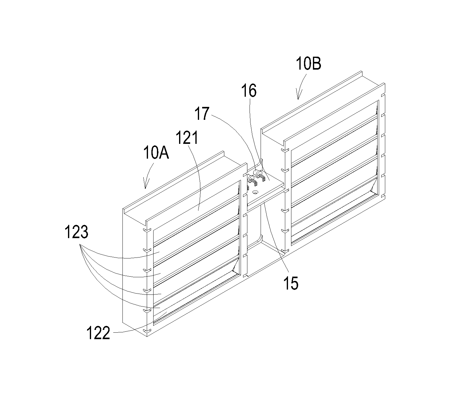
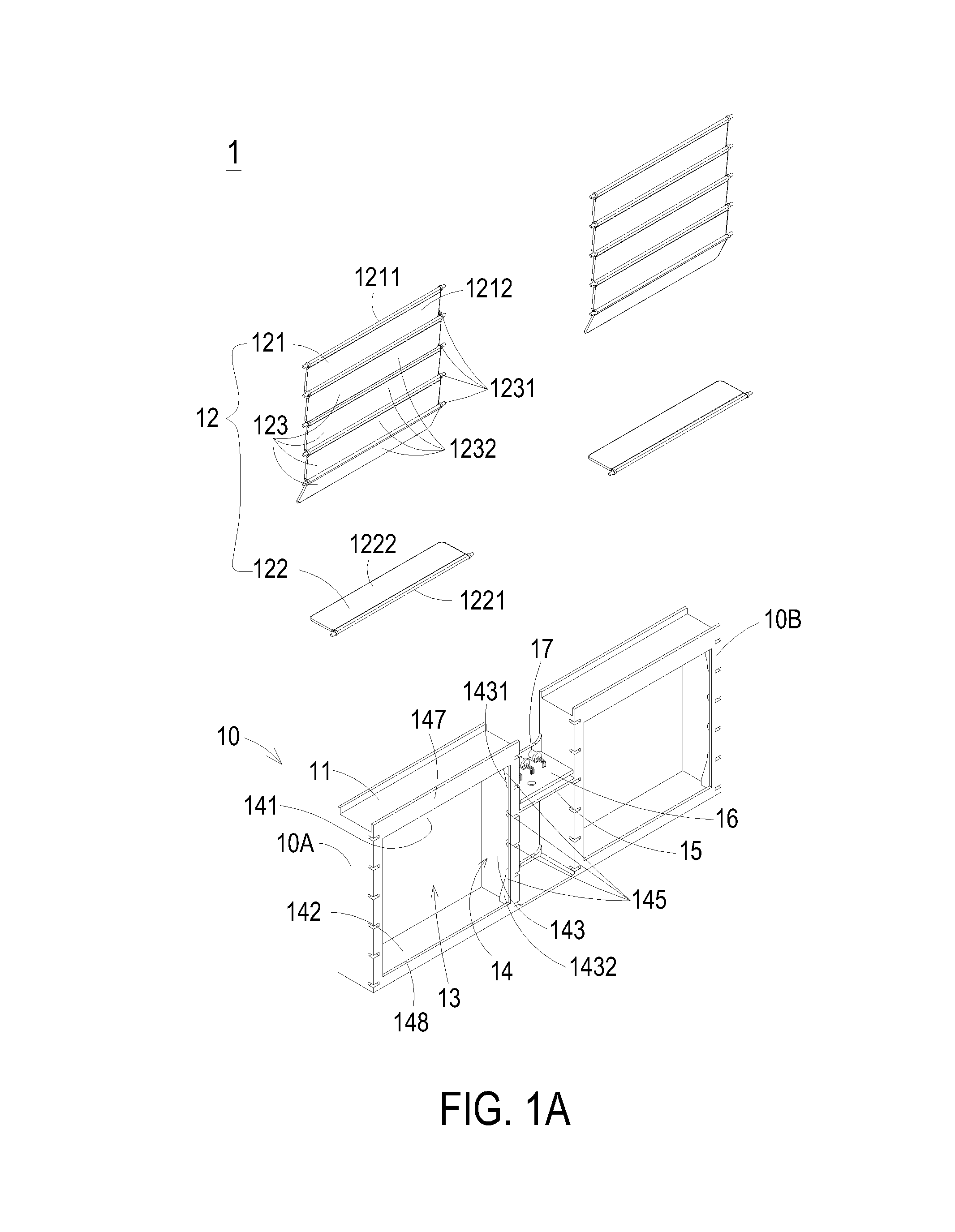
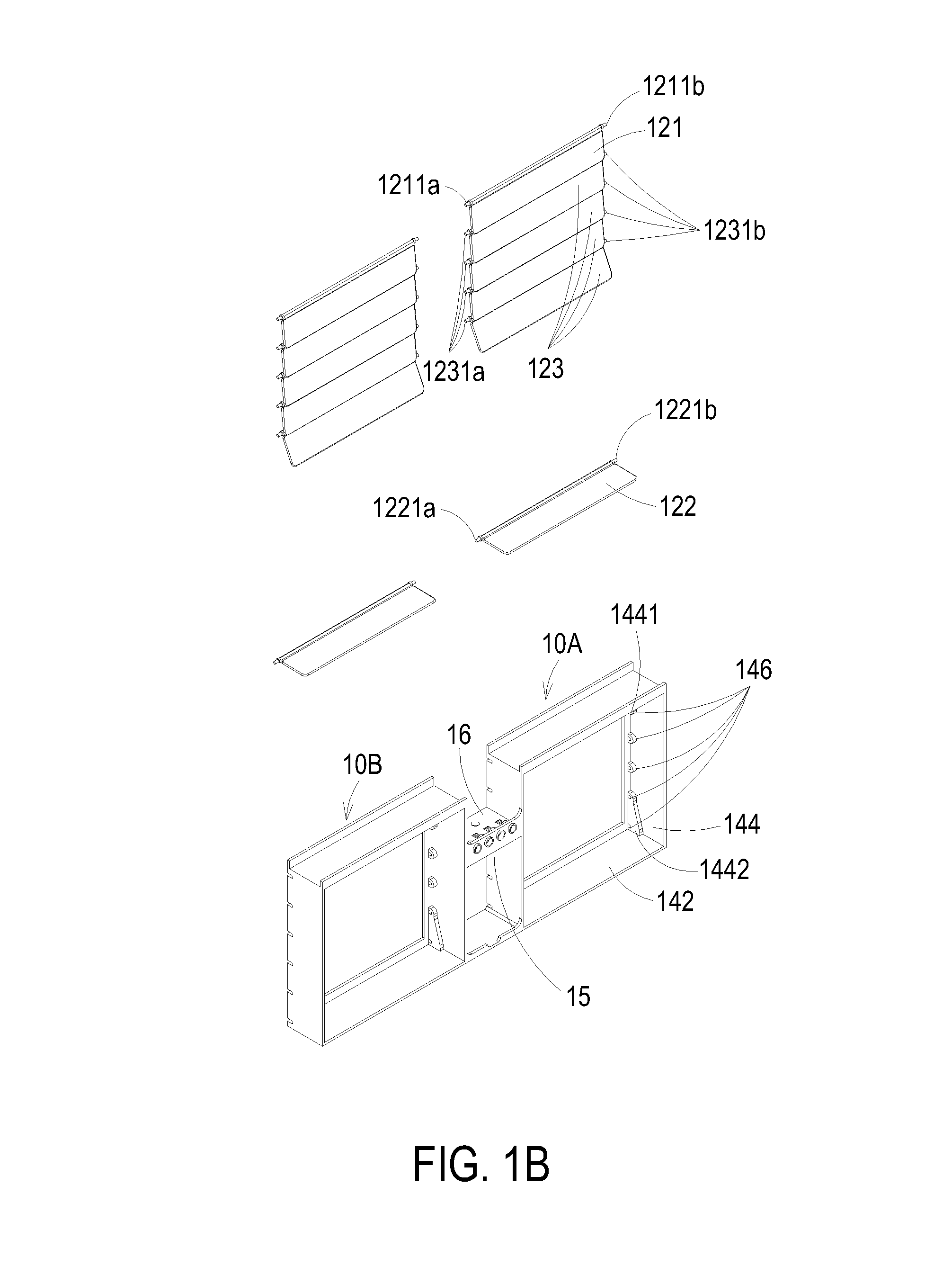
[0019]FIGS. 1A and 1B are schematic exploded views illustrating a backflow prevention device according to an embodiment of the present invention and taken along different viewpoints. FIGS. 2A and 2B are schematic assembled views illustrating the backflow prevention device of FIGS. 1A and 1B, respectively. Please refer to FIGS. 1A and 1B and FIGS. 2A and 2B. The backflow prevention device 1 comprises one or more backflow prevention units 10. In this embodiment, the backflow prevention device 1 comprises two backflow prevention units 10, including a first backflow prevention unit 10A and a second backflow prevention unit 10B. Each ...


PUM


Abstract

A backflow prevention device includes at least one backflow prevention unit. The backflow prevention unit includes a frame, a first edge shutter plate, a second edge shutter plate and plural intermediate shutter plates. The frame includes an airflow channel. If the first inner sidewall is disposed over the second inner sidewall, the first edge shutter plate and the plural intermediate shutter plates are configured to open or close the airflow channel, and the slab of the second edge shutter plate is inactive. Whereas, if the second inner sidewall is disposed over the first inner sidewall, the second edge shutter plate and the plural intermediate shutter plates are configured to open or close the airflow channel, and the slab of the first edge shutter plate is inactive.

Description

FIELD OF THE INVENTION[0001]The present invention relates to a backflow prevention device, and more particularly to a backflow prevention device for preventing backflow when the backflow prevention device stands upright or upside-down. The present invention also relates to a fan assembly having such a backflow prevention device.BACKGROUND OF THE INVENTION[0002]With increasing development of science and technology, a variety of power supply apparatuses or electronic devices are developed toward minimization, high integration and high power. As known, the natural convection is insufficient to remove the heat that is generated by the electronic components. If the heat fails to be effectively dissipated away, the elevated operating temperature may result in damage, reduced use life or deteriorated performance of the electronic components. For effectively removing the heat, the power supply apparatus or the electronic device should be equipped with a forced convection mechanism to exhaus...

Claims


Application Information

Patent Timeline
Patent Type & Authority Patents(United States)
IPC IPC(8): F24F7/00F16K15/03F24F13/06F24F13/08F04D25/14
CPCF16K15/035Y10T137/3149F04D25/14H05K7/2019F04D25/166
Inventor LI, RAN
Owner DELTA ELECTRONICS (THAILAND) PUBLIC CO LTD
Why Eureka
Try Eureka