Ultrasonic receiving circuit

a technology of ultrasonic receiving circuit and occupancy sensor, which is applied in the direction of reradiation, pulse technique, instruments, etc., can solve the problems of limiting the ability to detect small-magnitude ultrasonic waves with a doppler shift, circuit is very sensitive to thresholds, and receives ultrasonic waves are difficult to distinguish from received ultrasonic waves

Active Publication Date: 2015-10-13
LUTRON TECH CO LLC
View PDF16 Cites 16 Cited by
  • Summary
  • Abstract
  • Description
  • Claims
  • Application Information

AI Technical Summary

Problems solved by technology

One of the issues with detecting ultrasonic waves having a Doppler shift is that these received ultrasonic waves can be difficult to distinguish from the received ultrasonic waves that do not have a Doppler shift.
The drawback of this implementation is that the circuit is very sensitive to the thresholds of the comparators and only works on signals with an SIR greater than approximately −40 dB.
This implementation depends on the accuracy of the ADC of the microcontroller and is limited by numerical noise due to the ADC quantization and the numerical precision used to calculate the results, which thus limits the ability to detect small-magnitude ultrasonic waves that have a Doppler shift.

Method used


Image

  • Ultrasonic receiving circuit
  • Ultrasonic receiving circuit
  • Ultrasonic receiving circuit

Examples


Embodiment Construction

[0026]The foregoing summary, as well as the following detailed description of the preferred embodiments, is better understood when read in conjunction with the appended drawings. For the purposes of illustrating the invention, there is shown in the drawings an embodiment that is presently preferred, in which like numerals represent similar parts throughout the several views of the drawings, it being understood, however, that the invention is not limited to the specific methods and instrumentalities disclosed.

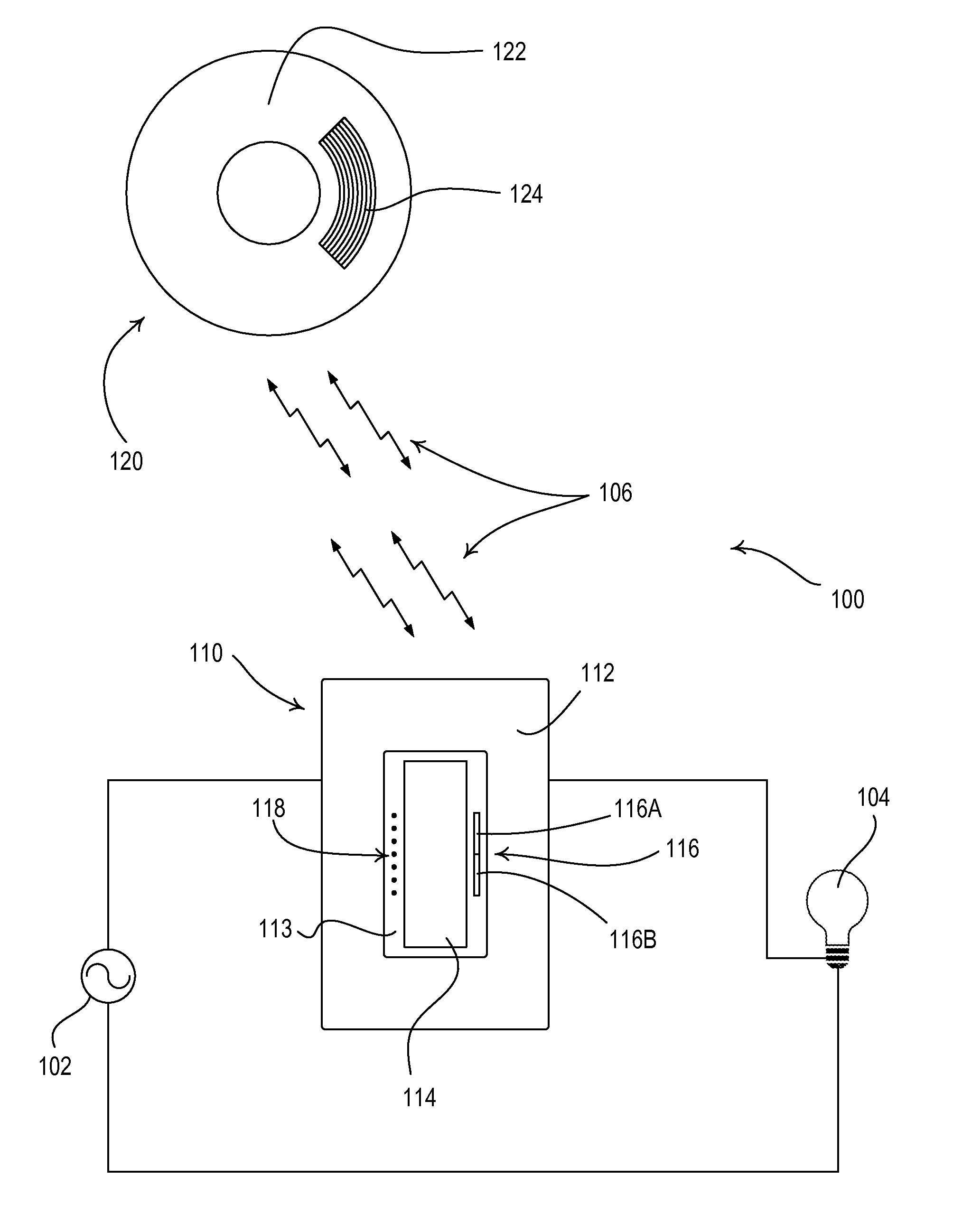
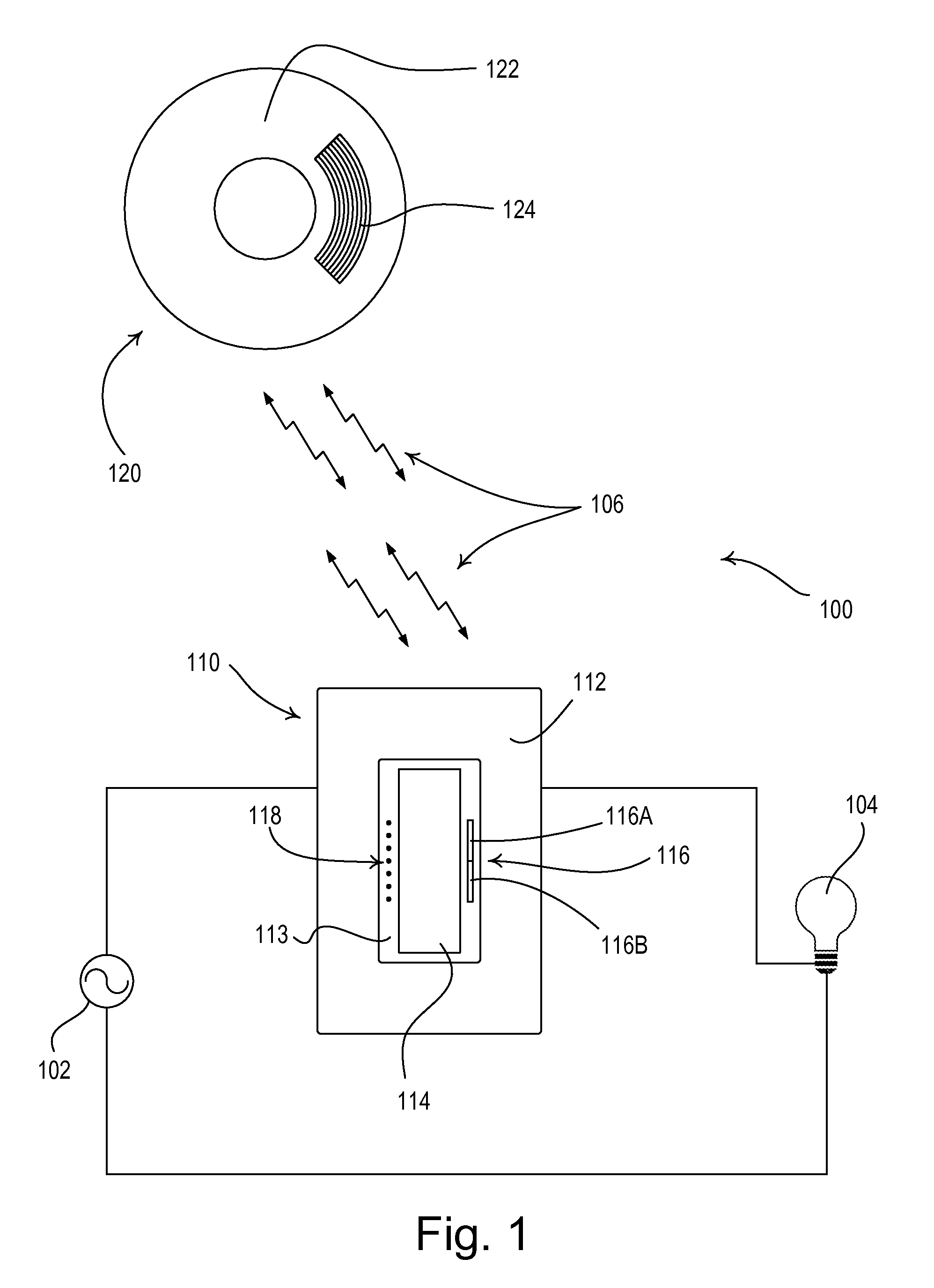
[0027]FIG. 1 is a simple diagram of a radio-frequency (RF) lighting control system 100 comprising a dimmer switch 110 and a remote ultrasonic occupancy sensor 120. The dimmer switch 110 is adapted to be coupled in series electrical connection between an AC power source 102 and a lighting load 104 for controlling the amount of power delivered to the lighting load. The dimmer switch 110 may be adapted to be wall-mounted in a standard electrical wallbox. Alternatively, the dimmer s...


PUM

PropertyMeasurementUnit
frequency fOPaaaaaaaaaa
frequencyaaaaaaaaaa
frequencyaaaaaaaaaa

Abstract

An ultrasonic occupancy sensor for detecting presence or absence of an occupant in a space includes an ultrasonic receiving circuit having a synchronous rectifier that allows the circuit to detect small-magnitude ultrasonic waves having a Doppler shift. The sensor comprises an ultrasonic transmitter for transmitting ultrasonic waves at an ultrasonic operating frequency, and a controller that drives the transmitting circuit with complementary drive signals to control the ultrasonic operating frequency. The synchronous rectifier receives the drive signals from the controller and rectifies an amplified input signal to generate a rectified signal, which is filtered by a filter to generate a filtered signal. The controller receives the filtered signal and determines that the space is occupied if the magnitude of the filtered signal exceeds a threshold. The ultrasonic occupancy sensor may also include a low phase-noise oscillator circuit coupled to the controller for setting an internal operating frequency of the controller.

Description

CROSS-REFERENCE TO RELATED APPLICATIONS[0001]This application is a continuation-in-part application of commonly-assigned U.S. patent application Ser. No. 13 / 947,732, filed Jul. 22, 2013, which is a continuation of U.S. patent application Ser. No. 13 / 052,418, filed Mar. 21, 2011, now U.S. Pat. No. 8,514,075, issued Aug. 20, 2013, which is a non-provisional application of commonly-assigned U.S. Provisional Application No. 61 / 316,011, filed Mar. 22, 2010, all entitled ULTRASONIC RECEIVING CIRCUIT, the entire disclosures of which are hereby incorporated by reference.BACKGROUND OF THE INVENTION[0002]1. Field of the Invention[0003]The present invention relates to occupancy and vacancy sensors for detecting an occupancy or a vacancy in a space, and more particularly, to an ultrasonic receiving circuit for an occupancy or vacancy sensor.[0004]2. Description of the Related Art[0005]Occupancy and vacancy sensors are often used to detect occupancy and / or vacancy conditions in a space in order ...

Claims


Application Information

Patent Timeline
Patent Type & Authority Patents(United States)
IPC IPC(8): G08B13/08G01N29/34
CPCG01N29/348G01S7/521G01S15/04G08B13/1627H03K2217/960705H05B47/115Y02B20/40
Inventor STEINER, JAMES P.
Owner LUTRON TECH CO LLC
Why Eureka
Try Eureka