Power supply with output protection and control method of the power supply

a power supply and output protection technology, applied in the field of power supplies, can solve the problems of high cost of high-performance power supplies, power supply and load damage, and ineffective protection functions of over-current protection functions, and achieve the effect of preventing a high booting curren

Active Publication Date: 2015-10-13
ACBEL POLYTECH INC
View PDF5 Cites 2 Cited by
  • Summary
  • Abstract
  • Description
  • Claims
  • Application Information

AI Technical Summary

Benefits of technology

[0012]An objective of the invention is to provide a power supply with output protection and a control method of the power supply. The power supply of the invention is adapted to compare a present output current with an over-current protection value and a pre-protection value lower than the over-current protection value. The output of the power supply is effectively protected. Furthermore, a user can use the power supply of the invention for decreasing cost, eliminating the need for using the high-performance one.
[0023]In short, a power supply executing the method of the invention is capable of enduring a high booting current by properly setting the over-current protection value. Expensive high-performance power supply is not needed.
[0039]The output current of the booting power supply does not cause other abnormal phenomena, i.e. causing abnormal high temperature due to over-load. When the power supply works in a steady state, the method of the invention takes the over-current protection action until the output current abnormally rises due to over-load. By using the method of the invention, a manufacturer can properly set the over-current protection value to prevent a high booting current from accidently trigging the over-current protection action. The power supply of the invention still effectively practices the objective of output protection.

Problems solved by technology

The power supply and the load will be easily damaged due to the over-current condition if the over-current protection point is too high.
On the other hand, if the over-current protection point is too low, the over-current protection function will not effectively protect the power supply and the load.
A user has to choose an expensive high-performance power supply to prevent a high booting current from accidently triggering the protection action.
The high-performance power supply is usually much expensive than a general one.
The cost for building a power system with the high-performance power supply is high.

Method used


Image

  • Power supply with output protection and control method of the power supply
  • Power supply with output protection and control method of the power supply
  • Power supply with output protection and control method of the power supply

Examples


Embodiment Construction

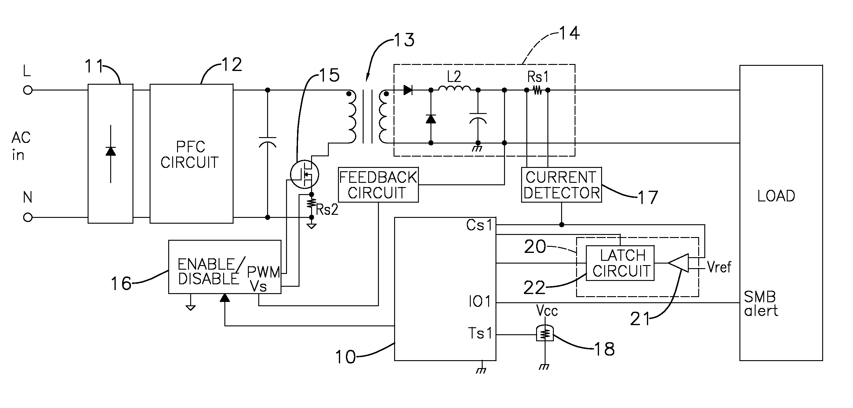
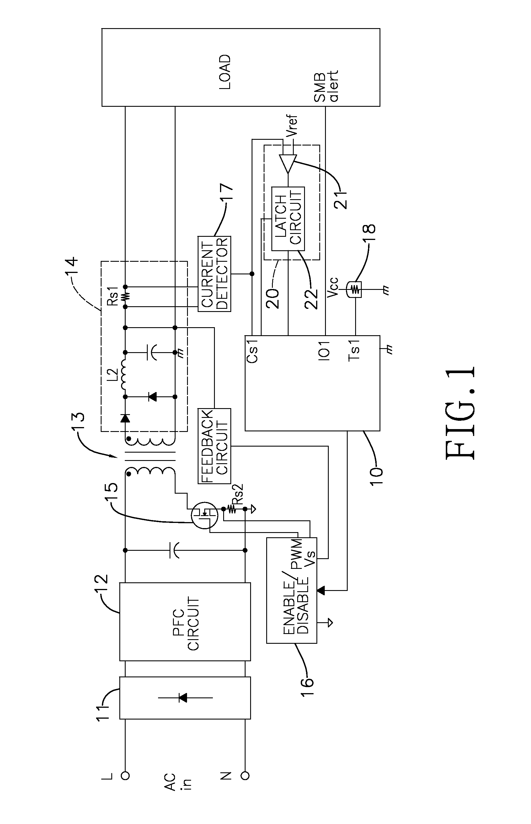
[0044]With reference to FIG. 1, the power supply of a first embodiment of the invention comprises a rectifier circuit 11, a PFC (Power Factor Correction) circuit 12, a transformer 13, an output circuit 14, a power switch device 15, a PWM (Pulse Width Modulation) controller 16, a microcontroller 10 and a current detector 17.

[0045]An input terminal of the PFC circuit 12 is connected to a DC output terminal of the rectifier circuit 11. The transformer 13 has a primary side and a secondary side. The primary side is connected to an output terminal of the PFC circuit 12. An input terminal of the output circuit 14 is connected to the secondary side of the transformer 13. The power switch device 15 can be a power transistor. The power switch device 15 is connected to the primary side of the transformer 13 and is turned on or turned off by the PWM controller 16.

[0046]The PWM controller 16 has a feedback input terminal (Vs), an enable / disable terminal (ENABLE / DISABLE) and a PWM signal output ...


PUM


Abstract

The present invention relates to a power supply with output protection and a control method of the power supply. The invention mainly provides a pre-protection value lower than a default over-current protection value. When a present output current of the power supply is higher than or equal to the pre-protection value and is lower than the over-current protection value, the method firstly determines whether the power supply has abnormal conditions. When the power supply has abnormal conditions, the method can automatically provide or stop providing a working voltage to a load. When the present output current is further higher than or equal to the over-current protection value, the method takes an over-current protection action. By multi-level monitoring of the current values, the invention properly provides an over-current protection.

Description

CROSS-REFERENCE TO RELATED APPLICATIONS[0001]This application claims the benefit of Taiwan patent application No. 101139031, filed on Oct. 23, 2012, the disclosure of which is incorporated herein in its entirety by reference.BACKGROUND OF THE INVENTION[0002]1. Field of the Invention[0003]The present invention relates to a power supply, and more particularly to a power supply with output protection and a control method of the power supply.[0004]2. Description of Related Art[0005]With reference to FIG. 4, a circuit diagram of a conventional power supply is disclosed. The conventional power supply has a rectifier circuit 81, a PFC (Power Factor Correction) circuit 82, a transformer 83, an output circuit 84, a power switch device 85, a PWM (Pulse Width Modulation) controller 86, a feedback circuit 87 and a microcontroller 88.[0006]An input terminal of the output circuit 84 is connected to a secondary side of the transformer 83. An output terminal of the output circuit 84 is connected to...

Claims


Application Information

Patent Timeline
Patent Type & Authority Patents(United States)
IPC IPC(8): H02H3/08
CPCH02H3/085
Inventor CHEN, WEI-DAR
Owner ACBEL POLYTECH INC
Why Eureka
Try Eureka