Ophthalmologic apparatus and control method of the same

a technology of ophthalmologic equipment and control method, which is applied in the field of ophthalmologic equipment, can solve the problems of reducing the clarity of ophthalmologic images, reducing the accuracy of diagnosis or treatment, and affecting the influence of eye movement during photographing

Active Publication Date: 2015-10-20
CANON KK
View PDF39 Cites 18 Cited by
  • Summary
  • Abstract
  • Description
  • Claims
  • Application Information

AI Technical Summary

Benefits of technology

[0014]The present invention has another object to shorten an imaging time by selecting a fundus image that is less affected by eye motion.
[0018]According to the present invention, a fundus image can be selected that is less affected by eye motion in extraction of a template image.

Problems solved by technology

However, in medical practice using ophthalmologic images, the influence of eye movement during photographing has been recognized as a serious problem for long years.
Specifically, eye movement may reduce clarity of ophthalmologic images to prevent an increase in accuracy of diagnosis or treatment.
However, the technique disclosed in the document troublesomely requires addition of hardware for detecting eye movement besides an ophthalmoscope.
In detecting movement of fundus in pattern matching using a template image, a selected template image does not match an area to be detected or matches an area that is not to be detected in some cases, thereby causing false detection.
However, in the conventional method, whether a fundus image is a proper image is not determined in extraction of a template image.
Thus, if pattern matching is not completed, a template image needs to be again extracted during imaging, which increases time and work for extracting a template image, and inevitably places burdens on an operator and a patient.
Thus, it cannot be determined whether the small area is proper, and a small area needs to be again selected when matching is not completed, which increases burdens on an operator and a patient.
However, since a step is necessary of acquiring and synthesizing a plurality of tomographic images and further converting the images into a lateral image of the fundus, the movement cannot be detected at high speed during imaging.
Also, Japanese Patent No. 04466968 does not disclose a technique of extracting a template image to execute tracking.

Method used


Image

  • Ophthalmologic apparatus and control method of the same
  • Ophthalmologic apparatus and control method of the same
  • Ophthalmologic apparatus and control method of the same

Examples


embodiment 1

[0033](Embodiment 1)

[0034]An embodiment of the present invention will be described in detail with reference to the drawings.

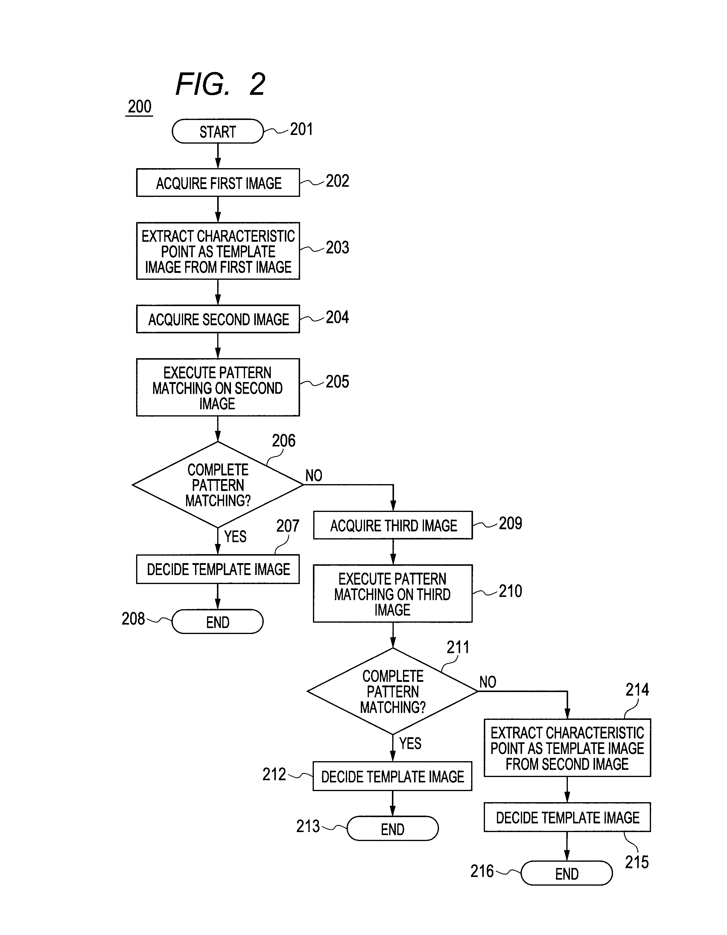
[0035]In this embodiment, a scanning laser ophthalmoscope (SLO) to which the present invention is applied will be described. In particular, an apparatus will be herein described that extracts a template image from a picked-up first fundus image, and executes pattern matching on a further picked-up second fundus image to evaluate a fundus image, and decides a template image for movement detection of an eye to be inspected for tracking. However, the present invention is not limited to this, but includes a method of evaluating an image using one or more fundus images with respect to the extracted template image (also referred to as a characteristic image).

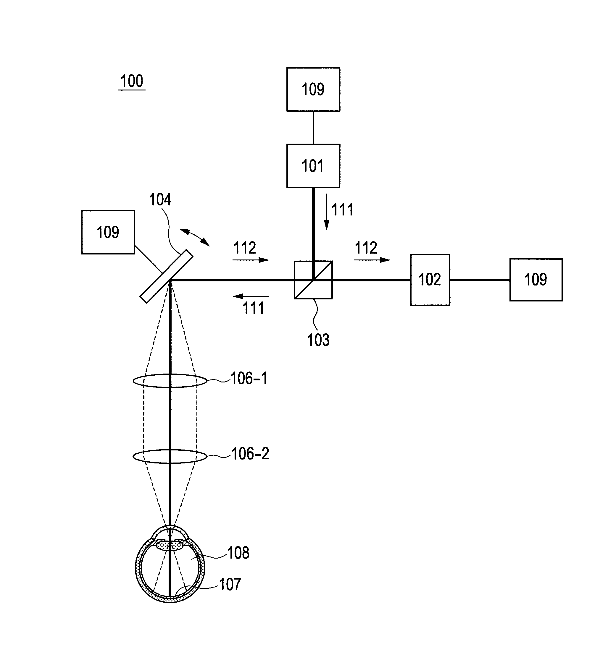
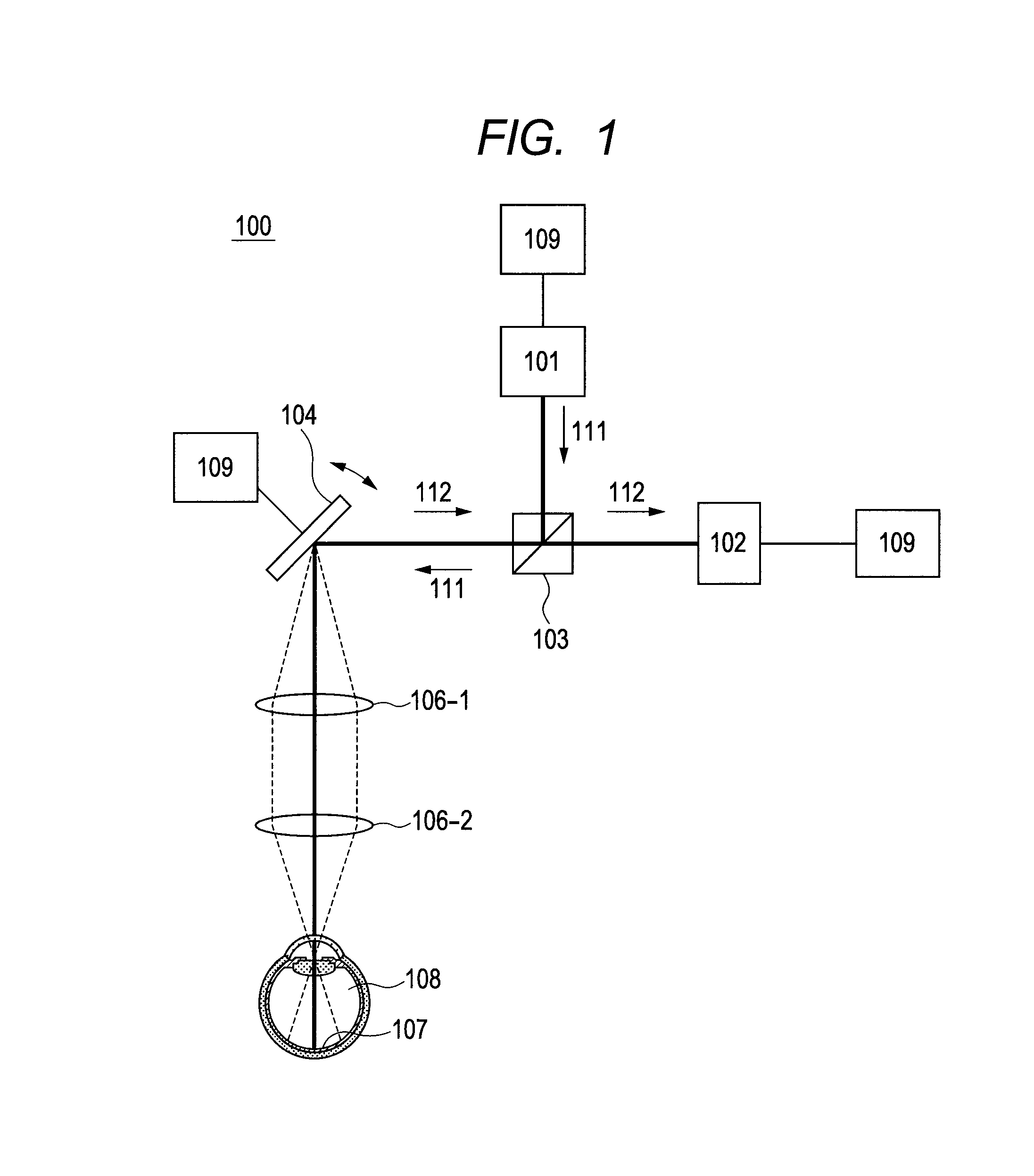
[0036](Fundus Image Photographing Apparatus: SLO)

[0037]First, with reference to FIG. 1, an entire schematic configuration of an optical system of a scanning laser ophthalmoscope (SLO: Scanning Laser Ophthalmoscop...

embodiment 2

[0069](Embodiment 2)

[0070]In this embodiment, a scanning laser ophthalmoscope (SLO) to which the present invention is applied will be described. In particular, an apparatus will be herein described that extracts template images from a plurality of picked-up fundus images, executes matching between the template images to evaluate the fundus images, and decides a movement detecting template image for tracking. With reference to FIGS. 1, 4 and 5, a method for evaluating fundus images using three fundus images will be particularly described in this embodiment.

[0071]This embodiment has the same configuration as Embodiment 1, and thus descriptions on the configuration will be omitted.

[0072](Acquiring of Fundus Image)

[0073]When an operator issues a command to acquire a fundus image through the memory-control-signal processing unit 109, the ophthalmologic imaging apparatus 100 acquires a plurality of fundus images (Step 402). In this embodiment, three fundus images: a first fundus image 501...

embodiment 3

[0085](Embodiment 3)

[0086]In Embodiment 3, an apparatus will be described that acquires areas around a coordinate arbitrarily decided by an operator as template images from a first fundus image, rather than extracts a characteristic point as a template image, and executes matching on a plurality of fundus images for evaluation. In this embodiment, with reference to FIGS. 1, 7, 8 and 9, an apparatus will be particularly described that executes pattern matching on second and third fundus images using a template image selected from a first fundus image.

[0087]This embodiment has the same configuration as Embodiment 1, and thus descriptions on the configuration will be omitted. Descriptions on parts overlapping Embodiments 1 and 2 will be omitted.

[0088](Acquiring of Fundus Image 1)

[0089]A first fundus image 801 from which a template image is acquired is acquired (Step 702). In this embodiment, a fundus image of 2000 pixels×2000 pixels in size is acquired.

[0090](Extraction of Template Ima...


PUM


Abstract

There is provided an ophthalmologic apparatus having a tracking function that can select a fundus image that is less affected by eye motion to reduce burdens on an operator / a patient in fundus imaging, wherein the ophthalmologic apparatus picks up a first fundus image (202), extracts a characteristic point as a template from the first fundus image (203), executes pattern matching on a second fundus image (205) to determine presence / absence of eye motion, and decides a tracking template image (207).

Description

BACKGROUND OF THE INVENTION[0001]1. Field of the Invention[0002]The present invention relates to an ophthalmologic apparatus and a control method thereof, and more particularly to an ophthalmologic apparatus that evaluates a fundus image used for extracting a template image in the case where pattern matching of a fundus image is executed in detection of biological motion, and a control method thereof.[0003]2. Description of the Related Art[0004]In recent years, ophthalmologic images typified by fundus images have been used in medical practice as medical images for early detection of diseases. However, in medical practice using ophthalmologic images, the influence of eye movement during photographing has been recognized as a serious problem for long years. Specifically, eye movement may reduce clarity of ophthalmologic images to prevent an increase in accuracy of diagnosis or treatment. Human eyes are repeating involuntary slight vibration even during fixation on one point. This is r...

Claims


Application Information

Patent Timeline
Patent Type & Authority Patents(United States)
IPC IPC(8): A61B3/14A61B3/10A61B3/00A61B3/113
CPCA61B3/113A61B3/0058A61B3/12
Inventor TOMATSU, NOBUHIROMAKIHIRA, TOMOYUKISUEHIRA, NOBUHITO
Owner CANON KK
Why Eureka
Try Eureka