Method for purging of air intake system hydrocarbon trap

a technology of hydrocarbon traps and air intake systems, applied in the direction of machines/engines, output power, electric control, etc., can solve the problems of fuel vapors, increase evaporative emissions, airflow across the trap, etc., and achieve the effect of increasing evaporative emissions

Active Publication Date: 2015-10-20
FORD GLOBAL TECH LLC
View PDF14 Cites 9 Cited by
  • Summary
  • Abstract
  • Description
  • Claims
  • Application Information

AI Technical Summary

Benefits of technology

[0002]Plug-in hybrid electric vehicles (PHEV) may include hydrocarbon (HC) traps coupled in an air induction system of the engine to adsorb evaporative emissions in the engine intake. For example, fuel vapors may result from fuel sprayed into the intake manifold, fuel leaked from fuel injectors and / or fuel puddled in the intake. These fuel vapors, if not stored in the hydrocarbon trap, may flow out of the intake system during engine shutdown, increasing evaporative emissions.
[0004]However the inventors herein have identified potential issues with such systems. The reduced engine operation time of PHEVs may limit the amount of intake manifold vacuum generated for hydrocarbon trap purging. As such, airflow across the trap may be limited, reducing passive desorption of fuel vapors. Incomplete purging of the hydrocarbon trap can result in an increase in intake evaporative emissions and degrade vehicle emissions performance.
[0005]The inventors herein have recognized the above issue and identified an approach to at least partly address the issue. In one example approach, a method for a hybrid vehicle with an engine including a HC trap in an intake of the engine is provided. The method comprises, during vehicle travel in an engine-off condition, increasing airflow through a HC trap and purging fuel vapors from the trap to a fuel system canister coupled to a fuel tank. In this way, a HC trap can be at least partially purged in an efficient way, even during conditions when the engine is not running.
[0006]For example, while operating the hybrid vehicle in an electric mode where wheel torque is provided by a system battery and an engine is maintained shutdown (e.g., at rest), HC trap purging may be enabled when there is sufficient vehicle motion-induced airflow. For example, once the vehicle speed exceeds a threshold, the intake throttle may be partially or fully opened to increase airflow through the intake system and past the HC trap. Concurrently, cylinder intake and exhaust valves may be closed (e.g., via cam timing adjustments), if not already closed, and a canister purge valve may be opened so as to route motion-inducted airflow containing released HCs from the HC trap to the fuel system. The purge fuel vapors desorbed from the HC trap can be routed into and through a fuel system canister so as to transport the stored HCs from the intake system to be stored in the fuel system. Intake airflow may also be further enhanced during the engine-off condition via adjustments to grill shutters and louvers, as well as by operating a cooling system fan.
[0007]In this way, intake fuel vapors stored in an air induction system HC trap may be opportunistically transferred to a fuel system canister with larger storage capacity for storage therein during engine-off conditions. By opening an intake throttle during vehicle travel in an electric mode, vehicle motion is advantageously used to generate airflow in a direction from ambient, to and along the hydrocarbon trap, and then to another storage location before finally venting to atmosphere. This enables the trap to be at least partially cleaned even while an engine is shutdown and no intake manifold vacuum is generated. By delivering the fuel vapors from the smaller capacity trap to a larger capacity fuel system canister, the canister may be used as a HC vapor “storage bank” so that the HC trap may be cleaned out more often until the engine is operated to clean out the canister (and the HC trap). This results in reduced HC breakthrough from the HC trap. Overall exhaust emissions and hybrid vehicle performance are thereby improved.

Problems solved by technology

For example, fuel vapors may result from fuel sprayed into the intake manifold, fuel leaked from fuel injectors and / or fuel puddled in the intake.
These fuel vapors, if not stored in the hydrocarbon trap, may flow out of the intake system during engine shutdown, increasing evaporative emissions.
Specifically, during engine operation, intake manifold vacuum draws the fuel vapors into the engine and also causes airflow across the trap, increasing desorption.
However the inventors herein have identified potential issues with such systems.
The reduced engine operation time of PHEVs may limit the amount of intake manifold vacuum generated for hydrocarbon trap purging.
As such, airflow across the trap may be limited, reducing passive desorption of fuel vapors.
Incomplete purging of the hydrocarbon trap can result in an increase in intake evaporative emissions and degrade vehicle emissions performance.
This results in reduced HC breakthrough from the HC trap.

Method used


Image

  • Method for purging of air intake system hydrocarbon trap
  • Method for purging of air intake system hydrocarbon trap
  • Method for purging of air intake system hydrocarbon trap

Examples


Embodiment Construction

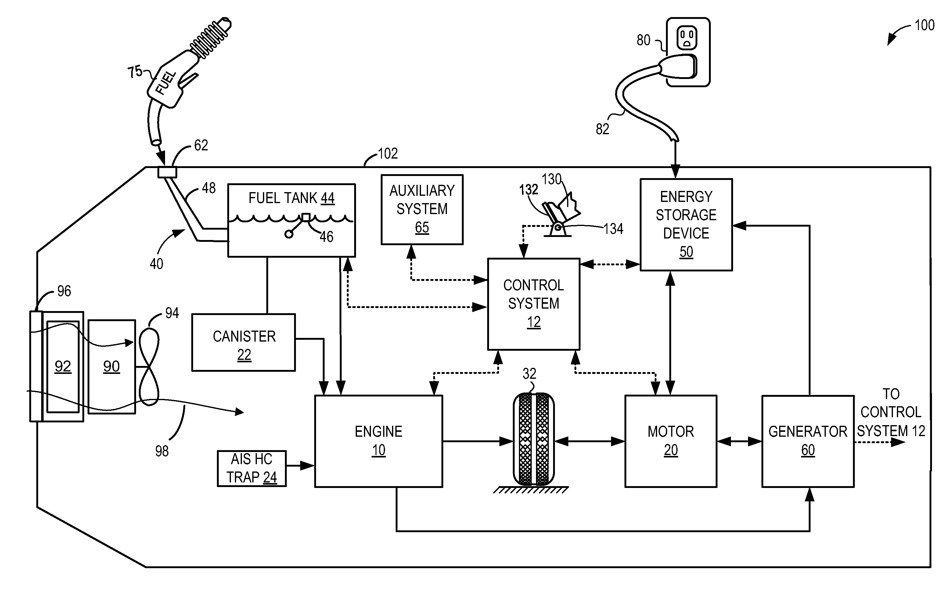
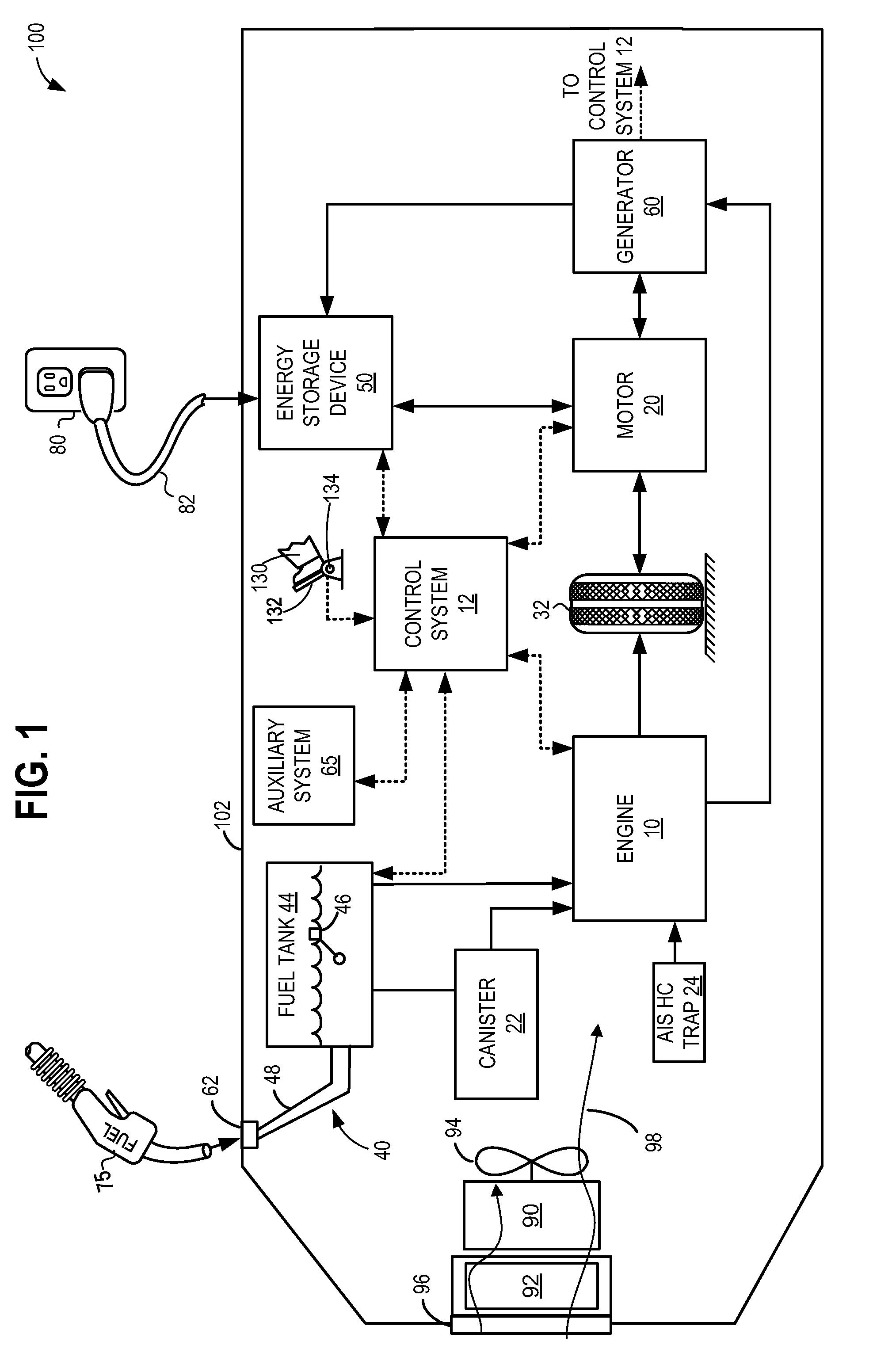
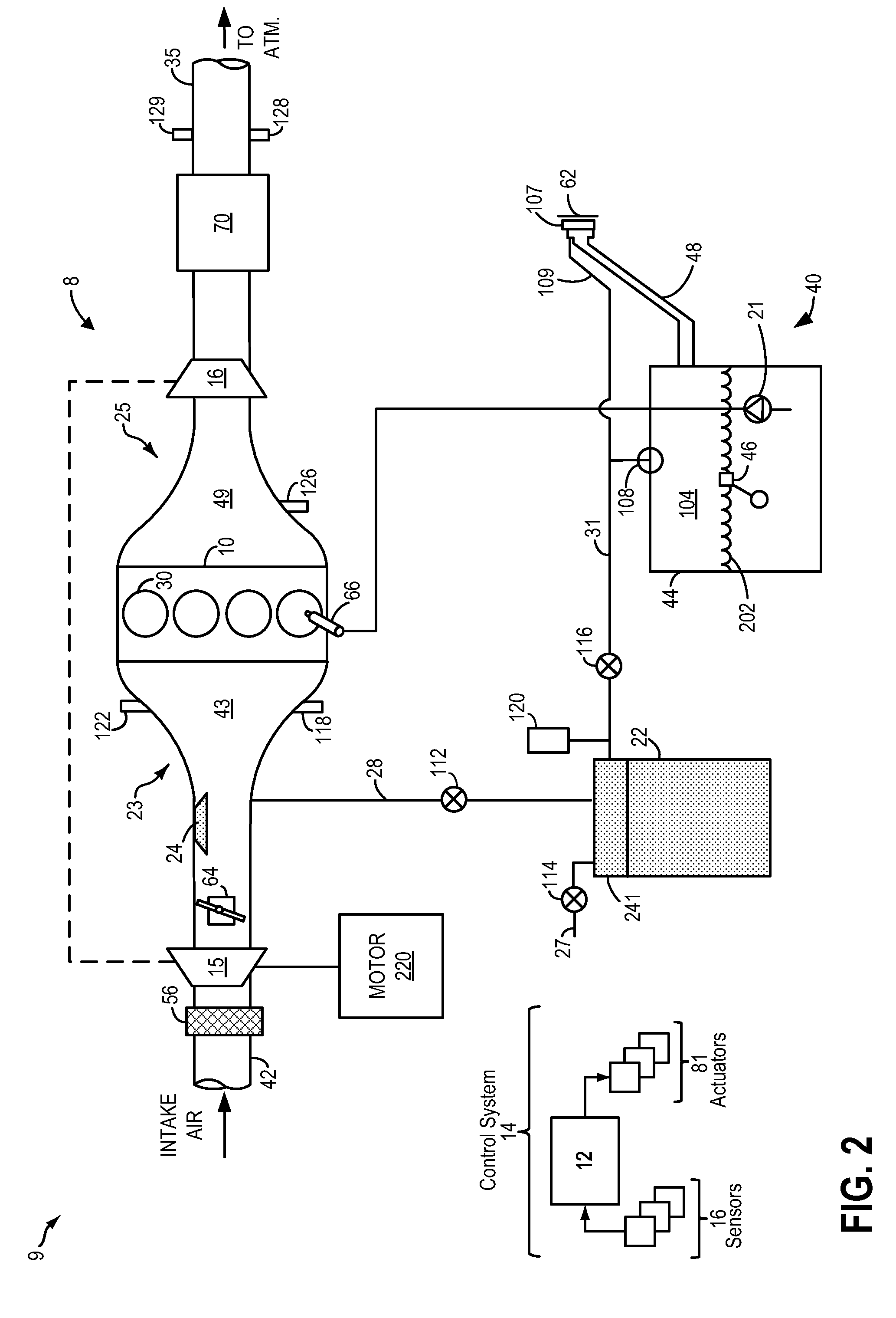
[0016]The following description relates to systems and methods for improving purging of a hydrocarbon (HC) trap situated in an engine intake, such as in the plug-in hybrid electric vehicle system of FIGS. 1 and 2. The HC trap is located within the air intake system (AIS) of an engine system, downstream of an intake throttle and upstream of the cylinders, as shown in FIG. 3. A controller may be configured to perform a routine, such as the example routine of FIG. 4, to open an intake throttle and canister purge valve (CPV), while closing cylinder valves (if not already closed) during vehicle travel in an electric-only mode to generate an airflow in the direction of the HC trap, allowing for improved desorption of fuel vapors from the HC trap. The controller can also perform a routine, such as that of FIG. 5, to purge the fuel system canister when the engine is operational. The CPV may be opened based on various vehicle operating conditions to expedite transfer of fuel vapors from the ...


PUM


Abstract

Methods and systems are provided for improving air intake system hydrocarbon trap purging during engine-off time in a hybrid electric vehicle. One method includes opening the throttle during vehicle motion under battery operation and allowing airflow through the trap to purge its contents into the fuel canister via the canister purge valve. Upon transition into the engine-on mode, fuel vapors are released from the canister into the engine intake.

Description

FIELD[0001]The present description relates to a hydrocarbon trap in an intake system of an engine of a hybrid vehicle.BACKGROUND AND SUMMARY[0002]Plug-in hybrid electric vehicles (PHEV) may include hydrocarbon (HC) traps coupled in an air induction system of the engine to adsorb evaporative emissions in the engine intake. For example, fuel vapors may result from fuel sprayed into the intake manifold, fuel leaked from fuel injectors and / or fuel puddled in the intake. These fuel vapors, if not stored in the hydrocarbon trap, may flow out of the intake system during engine shutdown, increasing evaporative emissions.[0003]Example hydrocarbon traps are shown by Moyer et al in US 2013 / 0228145 and Burke et al. in US 2006 / 0054142. The hydrocarbon traps are positioned in the intake system so that fuel vapors can be passively adsorbed in and released from the hydrocarbon trap. Specifically, during engine operation, intake manifold vacuum draws the fuel vapors into the engine and also causes a...

Claims


Application Information

Patent Timeline
Patent Type & Authority Patents(United States)
IPC IPC(8): B60L11/00F02M25/08B60W10/08B60W10/06B60W20/00F02D41/00F02D11/10F02D13/02F02D29/02F02D41/04
CPCF02D41/0032B60W10/06B60W10/08B60W20/00F02D11/10F02M25/089F02D13/0215F02D29/02F02D41/042Y10S903/93B60K2015/0358B60W20/16B60W2710/0605B60Y2200/92B60Y2300/64Y02T10/62
Inventor DUDAR, AED M.YANG, DENNIS SEUNG-MANWATKINS, TIMOTHY
Owner FORD GLOBAL TECH LLC
Why Eureka
Try Eureka