Wideband analog bandpass filter

a wideband analog bandpass and filter technology, applied in the field of analog bandpass filter, can solve the problems of less than desirable linearity and the inability to provide independent control of frequency and bandwidth, and achieve the effect of high linearity

Active Publication Date: 2015-10-20
HITTITE MICROWAVE LLC
View PDF13 Cites 6 Cited by
  • Summary
  • Abstract
  • Description
  • Claims
  • Application Information

AI Technical Summary

Benefits of technology

[0006]It is therefore an object of this invention to provide a bandpass filter that has high linearity.
[0010]This invention features a bandpass filter which includes an RF input terminal; an RF output terminal; a plurality of electrically tunable coupling capacitors coupled in series between the RF input and output terminals; a plurality of resonating circuits each including an electrically tunable resonator capacitor coupled to one of the coupling capacitors; and at least one resistance coupled between the RF input and output terminals in series with at least one of the coupling capacitors for providing enhanced out of band rejection of the filter.
[0015]The invention also features a bandpass filter including an RF input terminal; an RF output terminal; a plurality of electrically tunable pairs of varactors coupled back-to-back in series between the RF input and output terminals; a plurality of resonating circuits each including an electrically tunable resonator capacitor coupled to one of the pairs of varactors; and at least one resistance coupled in series between at least one of the pairs of varactors for providing enhanced out of band rejection of the filter.

Problems solved by technology

One disadvantage of the filter in FIG. 1 is that its linearity is less than desirable.
As such, this filter cannot provide independent control of the frequency and the bandwidth.

Method used


Image

  • Wideband analog bandpass filter
  • Wideband analog bandpass filter
  • Wideband analog bandpass filter

Examples


Embodiment Construction

[0026]Aside from the preferred embodiment or embodiments disclosed below, this invention is capable of other embodiments and of being practiced or being carried out in various ways. Thus, it is to be understood that the invention is not limited in its application to the details of construction and the arrangements of components set forth in the following description or illustrated in the drawings. If only one embodiment is described herein, the claims hereof are not to be limited to that embodiment. Moreover, the claims hereof are not to be read restrictively unless there is clear and convincing evidence manifesting a certain exclusion, restriction, or disclaimer.

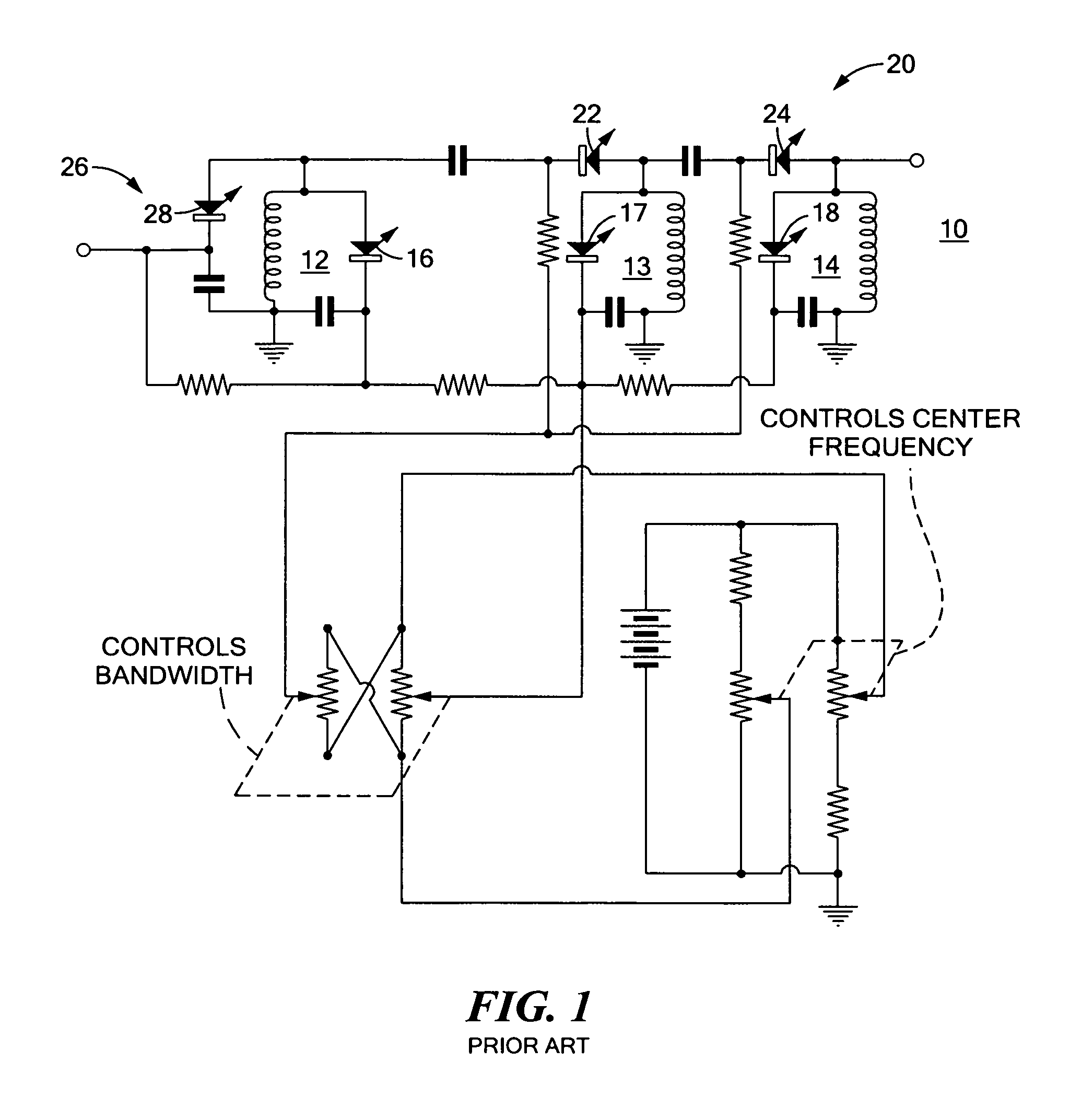
[0027]There is shown in FIG. 1 a prior tunable bandpass filter 10 that includes a multiple tuned resonator filter with each tuned section 12-14 incorporating a variable reactance device 16-18, i.e., a single varactor. Filter 10 also includes a reactive coupling network 20 with its own variable reactance devices 22, 24, and ...


PUM


Abstract

A wideband bandpass filter includes an RF input terminal, an RF output terminal, a plurality of electrically tunable coupling capacitors coupled in series between the RF input and output terminals, and a plurality of resonating circuits each including an electrically tunable resonator capacitor coupled to one of the coupling capacitors. At least one resistance is coupled in series between at least one of the coupling capacitors for providing enhanced out of band rejection of the filter.

Description

RELATED APPLICATIONS[0001]This application hereby claims the benefit of and priority to U.S. Provisional Application Ser. No. 61 / 337,474, filed on Feb. 4, 2010 under 35 U.S.C. §§119, 120, 363, 365, and 37 C.F.R. §1.55 and §1.78, which application is herein incorporated by reference.FIELD OF THE INVENTION[0002]This invention relates to an analog bandpass filter.BACKGROUND OF THE INVENTION[0003]There are many applications in which it is desirable to have a bandpass filter with high linearity such that a minimal amount of spurious are generated when subjected to an input spectrum with multiple tones. In some applications, it is also desirable for a bandpass filter to be tunable in both center frequency and bandwidth.[0004]Bandpass filters are known in the art. U.S. Pat. No. 3,110,004 relates to a prior tunable bandpass filter, FIG. 1, which includes a multiple tuned resonator filter with each tuned section including a variable reactance device, i.e., a single varactor. The filter also ...

Claims


Application Information

Patent Timeline
Patent Type & Authority Patents(United States)
IPC IPC(8): H03H7/01H03H7/12H03J3/26
CPCH03J3/26H03H7/0161H03H7/1775H03H2210/012H03H2210/015
Inventor KOECHLIN, MICHAEL
Owner HITTITE MICROWAVE LLC
Why Eureka
Try Eureka