

Fan
a fan and fan body technology, applied in the field of fans, can solve the problems of overheating of the circuit board, increasing production cost and time, and pollution of the environment, and achieve the effects of enhancing the air flowing effect inside the fan, the inside electronic components, and reducing the temperature of the motor
- Summary
- Abstract
- Description
- Claims
- Application Information
AI Technical Summary
Benefits of technology
Problems solved by technology
Method used
Image

Examples
Embodiment Construction
[0020]The present invention will be apparent from the following detailed description, which proceeds with reference to the accompanying drawings, wherein the same references relate to the same elements.
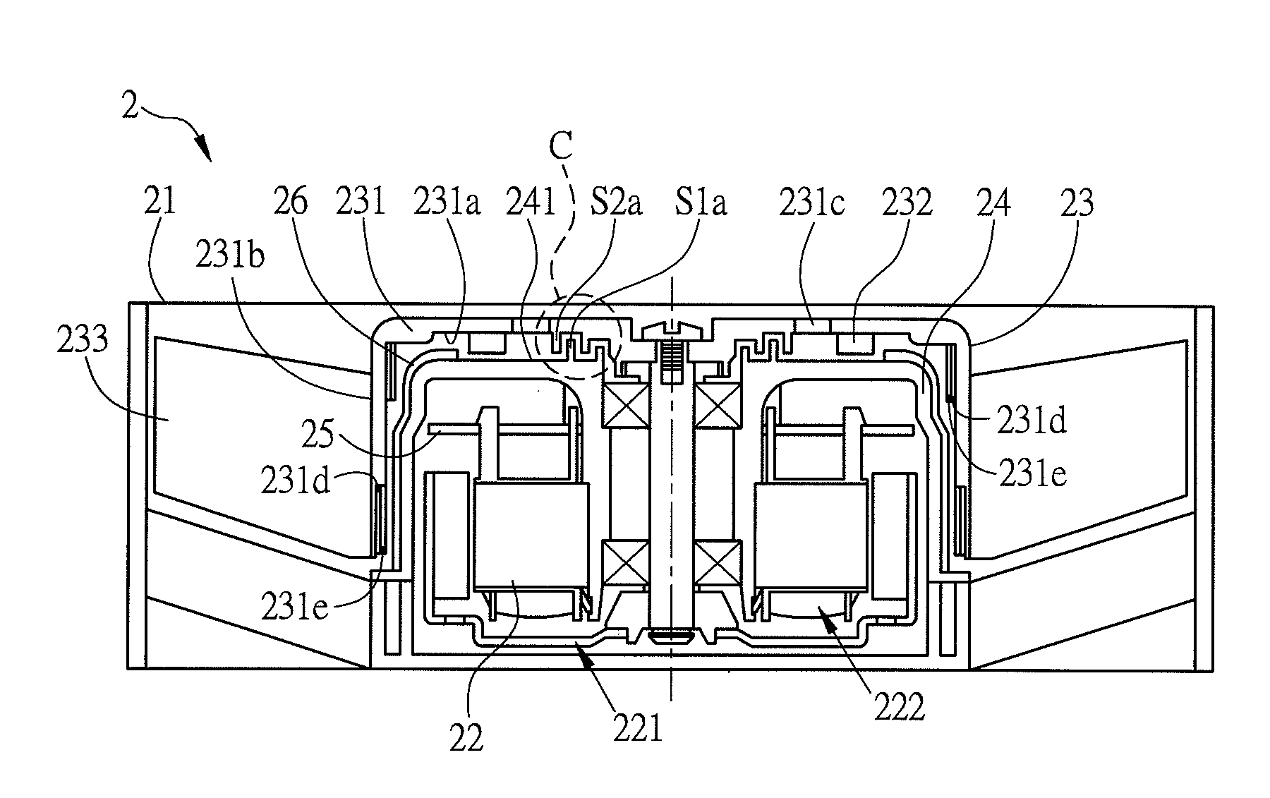
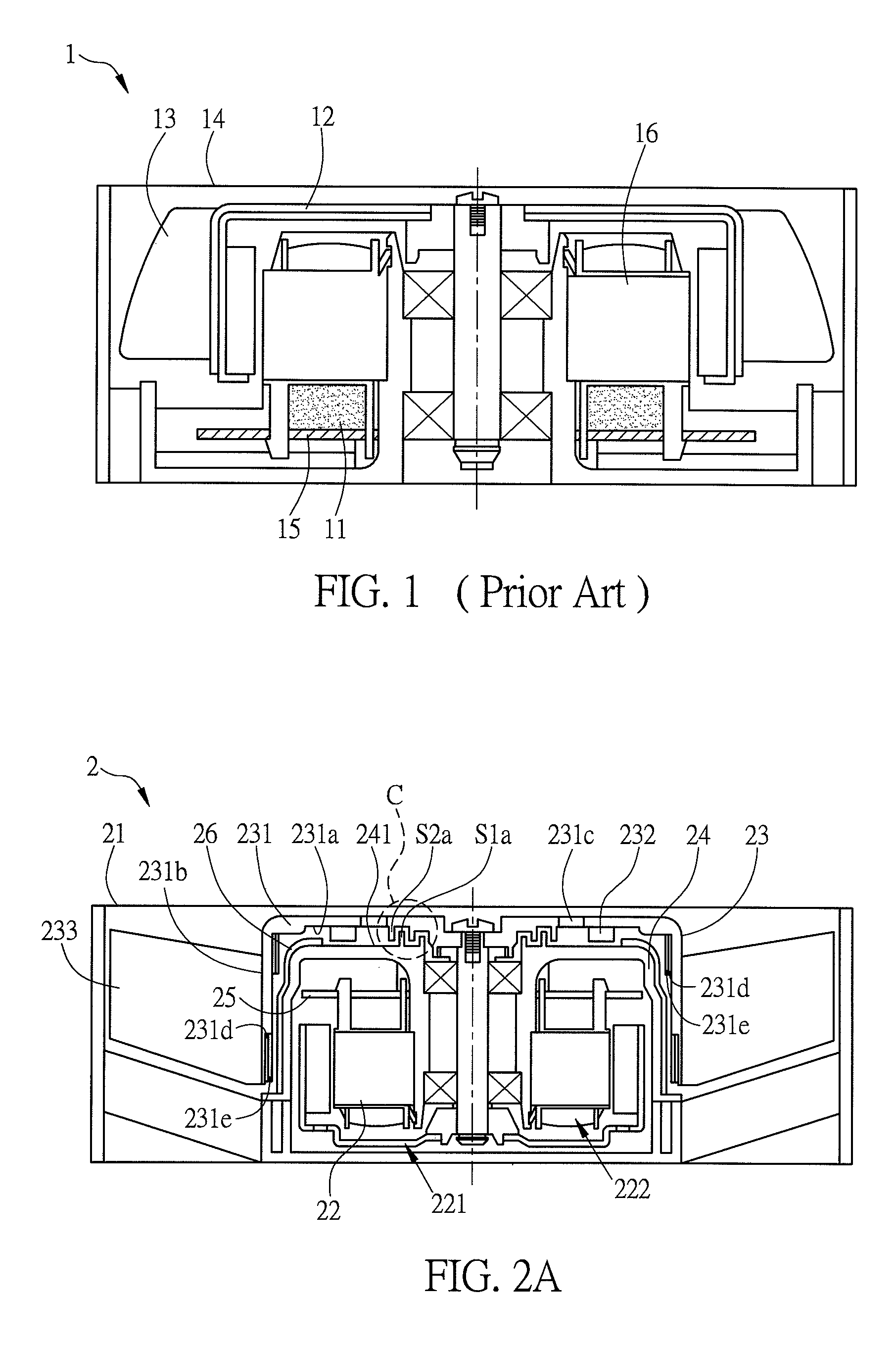
[0021]FIG. 2A is a schematic sectional diagram of a fan of a preferred embodiment of the invention. Referring to FIG. 2A, the fan 2 includes a fan frame 21, a motor 22 and an impeller 23. The motor 22 is disposed in the fan frame 21. The impeller 23 is connected with the motor 22 and driven by the motor 22. The fan 2 of the invention is, for example, a waterproof fan, suitable for the damp environment. The motor 22 can be assembled rightly or inversely. In this embodiment, since the circuit board 25 is disposed above the motor 22, the motor 22 is inversely assembled for example.
[0022]The impeller 23 includes a hub 231 and an outer blade 233. The hub 231 covers the motor 22, and has a first surface 231a and a second surface 231b opposite to the first surface 231a. The first surface 231...
PUM
 Abstract
Description
Claims
Application Information