Contact lens packaging

a technology for contact lenses and packaging, applied in the field of contact lens packaging, can solve the problems of lenses not resuming the desired curvature for optimum fit and/or optical correction, and the packaging disclosed therein is not useful for providing hydrogel contact lenses in a ready-to-wear form, so as to reduce the likelihood of spillage or mess

Active Publication Date: 2015-11-03
CONTACT LENS PRECISION LAB
View PDF13 Cites 19 Cited by
  • Summary
  • Abstract
  • Description
  • Claims
  • Application Information

AI Technical Summary

Benefits of technology

[0009]In one embodiment at least part of each package is formed of a material with a degree of resilient deformability, which assists in the formation of a snap fit closure. Preferably the packages are shaped such that a protruding part or section of one package forms a snap fit closure or the like with a correspondingly shaped recess on an adjacent package in the stack. Conveniently there is a reciprocal fit between the adjacent packages. By a “reciprocal fit” it is intended that each package is provided with both male and female portions which co-operate with reciprocal female and male portions on an adjacent package.
[0013]As noted above, adjacent members of the stack are joined, typically by a small amount of adhesive and / or a mechanical sealing fit, such that each contact lens is sealed in a substantially air tight manner, together with a small amount of an aqueous liquid, between the adjacent members of the stack. The ‘lid’ to each of the plurality of individual packages is thus essentially formed by the base of an overlying package. The invention thus dispenses with the need for a separate lid, such as a peelable film or foil, to be placed over each package in order to seal the contact lens in place.
[0014]It will be apparent that the outer surface of an upper package should not contact the inner surface of a cup-shaped portion of a lower package, at least over a portion thereof, so as to form the necessary cavity within which the contact lens may be accommodated. This can be accomplished by, for example, providing a raised profile on the peripheral portion of the lower package, and / or providing a downward projecting part on the underside of the upper package, and / or by ensuring that the respective surfaces of the upper and lower packages are not congruent.
[0015]It will be apparent to those skilled in the art that the size of the cavity formed between adjacent packages in a stack can be varied by altering the profile or shape of the respective surfaces of the adjacent packages. In this way, the maximum volume of aqueous liquid, such as aqueous saline or other solution, which can be accommodated in the cavity along with the lens, can be adapted to the desired circumstances. Thus, for example, a small volume of aqueous liquid (and correspondingly small volume cavity) may be employed if it is preferred to reduce the likelihood of spillage or mess when a package is opened by removing it from the stack. Conversely, a larger cavity and larger volume of aqueous liquid may be used if it is considered desirable to provide sufficient liquid in the package to allow the lens to be rinsed before insertion.
[0017]In particular, the concave cup-shaped portion of an upper package may desirably be at least partially accommodated within the concave cup-shaped portion of a lower package. More preferably the concave cup-shaped portion of the upper package is substantially accommodated in this way (e.g. at least 30% of the volume of the cup-shaped portion of the upper package is accommodated within the cup-shaped portion of the package beneath, preferably at least 40%, more preferably at least 50%). In this way, only a very small amount of aqueous liquid is required to keep a packaged contact lens hydrated. More importantly, the ‘dead’ volume of the packaging is substantially reduced, leading to more efficient use of materials and significant reduction in cost of manufacture, storage and transport of the packages, whilst still packaging the contact lens in its desired curved form so that it is not deformed or flattened by the packaging.
[0020]The packages in the stack may be essentially identical or they may for example possess a handedness. Conveniently a handedness may be imparted to the package by the position and / or shape of a flange portion. In one embodiment, a stack of packages may contain alternating left- and right-handed packages, in which the position and / or shape of a flange portion varies between the left and right handed packages. This alternating pattern creates a small gap between pairs of nearest left-handed packages and between pairs of nearest right-handed packages, to facilitate the insertion of a fingertip or fingernail etc. to separate a package from the stack.Materials

Problems solved by technology

Thus, for example, U.S. Pat. No. 6,260,695 discloses packaging for hydrogel contact lenses in a dehydrated state, such that the packaging disclosed therein is not useful for providing hydrogel contact lenses in a ready-to-wear form.
This is suitable for contact lenses formed of older style materials, but is not appropriate for contact lenses made using the latest silicone hydrogel materials, as it has been found that storing them in flattened form stretches them beyond their elastic limit, and when removed from the flattened packaging the lenses do not resume the desired curvature for optimum fit and / or optimum optical correction.

Method used


Image

  • Contact lens packaging
  • Contact lens packaging
  • Contact lens packaging

Examples


example 2

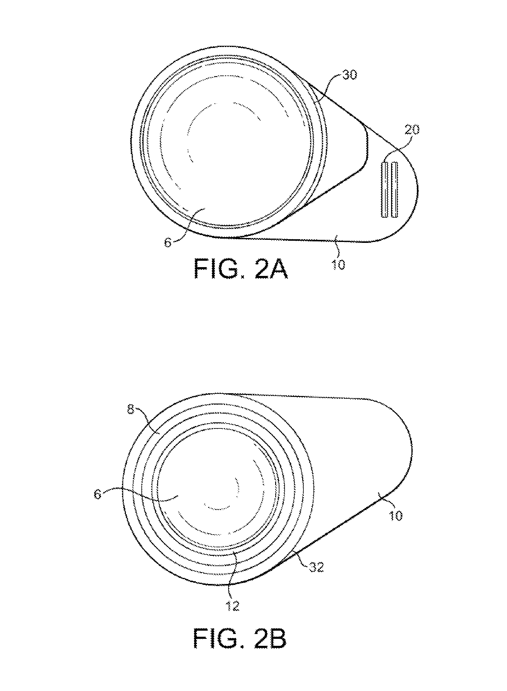
[0057]With reference to FIGS. 2A & 2B, this example describes in greater detail the application of adhesive to the adjacent packages.

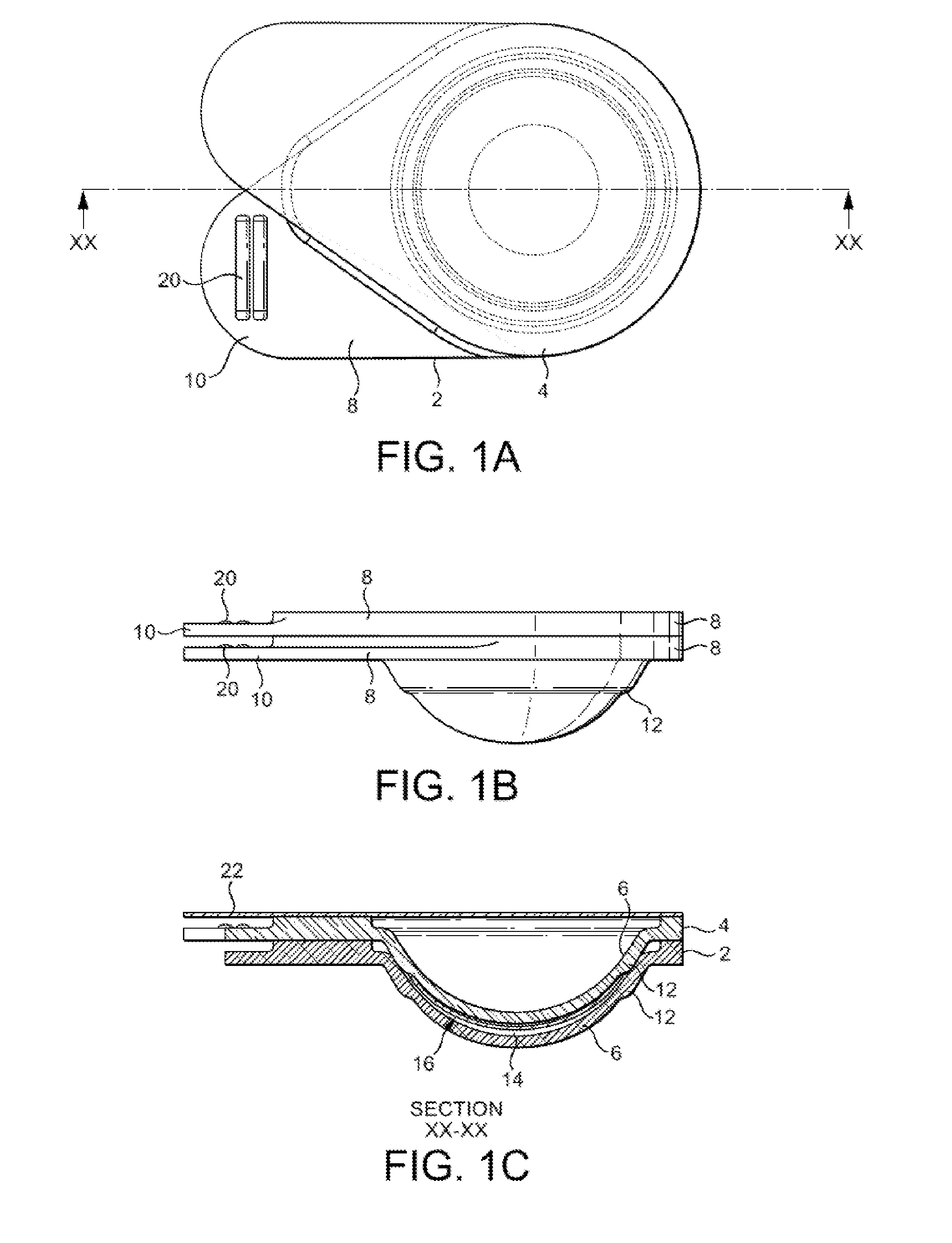
[0058]FIG. 2A shows a plan view looking down onto the upper surface of a package, identical to the embodiment illustrated in FIGS. 1A-1C. FIG. 2B is a plan view of the underside of the package. Parts equivalent to those in FIGS. 1A-1C are denoted by common reference numerals.

[0059]As explained elsewhere, the choice of adhesive may be determined at least in part by the choice of material used to form the packages. However, in a preferred embodiment, one side of the package will be formed (typically, moulded) so as to have a relatively rough surface. The other side of the package will be formed so as to have a relatively smooth surface. The adhesive composition will adhere preferentially to the relatively rough surface.

[0060]With reference to FIG. 2A, an annular part 30 on the upper surface of the peripheral portion 8 is formed with a relatively smooth s...

example 3

[0068]Referring to FIGS. 5A-5C, there is shown a holder for holding a stack of individually separable contact lens packages in accordance with the invention. More especially the holder is adapted and configured to hold a stack of the sort illustrated in FIGS. 4A-C.

[0069]The holder 50 is formed from a mouldable synthetic plastics material and comprises a flat, essentially horizontal base, 52, integrally formed with curved front and back upright members 54, 56 respectively. The upright members 54, 56 define between them a substantially vertical channel or groove within which the stack 58 of contact lens packages is accommodated. The inner face of the front upright member 54 is formed with two shallow indentations to accept the projecting flange portions of the left and right handed packages. The holder is also provided with an optional lid 60, which is slidably received within the same channel or groove which accommodates the stack of packages 58, the profile of the lid 60 being suita...

example 4

[0073]This example relates to an alternative arrangement of contact lens packages in a stack, as illustrated in FIGS. 8A-C.

[0074]In this embodiment, the individual packages are generally as shown in FIG. 1. However, the packages are all identical in shape and do not exist in left- or right-handed forms.

[0075]Instead, the individual packages are formed into a stack in which the projecting flange portions 10 are arranged so as to process in a manner rotating around the stack. In the embodiment shown, each flange portion is marked with a day of the week, the packaged lenses being intended for daily wear and subsequent disposal. The stack is arranged so as have rotational symmetry of order 7, such that the contact lens packages corresponding to a particular day of the week occupy the same relative rotational position within the stack.

[0076](Note that FIG. 8C is drawn to a different scale relative to FIGS. 8A & 8B).


PUM


Abstract

Disclosed is a stack of individually separable packages for a plurality of contact lenses, each individual lens being packaged between a first surface and a second surface, wherein the first surface is provided by a first one of the individually separable packages and the second surface is provided by a second one of the individually separable packages.

Description

[0001]This application claims priority to Great Britain Patent Application No. GB 1320153.8, filed Nov. 14, 2013, the disclosure of which is incorporated herein by reference.FIELD OF THE INVENTION[0002]The present invention relates to packaging for contact lenses, especially for silicone hydrogel contact lenses, and relates in particular to a plurality of separably joined individual packages, and to a method of making the same.BACKGROUND OF THE INVENTION[0003]It is well known to provide individual packaging for contact lenses. In particular, disposable contact lens for daily wear are often provided in horizontal strips of about 5 or 6 individual cases, each case containing a respective individual contact lens, with typically about 30 individual cases provided in a cardboard box (i.e. enough lenses for about 1 month for 1 eye).[0004]Daily-wear disposable lenses are conventionally formed of silicone hydrogel materials, which must be kept hydrated and in curved form, so that they are i...

Claims


Application Information

Patent Timeline
Patent Type & Authority Patents(United States)
IPC IPC(8): B65D85/00B65B55/16B65D83/08B65B17/02A45C11/00B65D21/02B65B25/00B65D81/22B65D71/50B65D43/02B65B55/22B65B55/08
CPCA45C11/005B65B17/02B65B25/008B65B55/08B65B55/16B65B55/22B65D21/0227B65D21/0228B65D43/02B65D71/50B65D81/22B65D83/0805B65D83/0817B65D2585/545A45C2011/006B65D21/0204B65D83/0409
Inventor CLAMP, JOHNNEWELL, RICHARD
Owner CONTACT LENS PRECISION LAB
Why Eureka
Try Eureka