
Method for producing a ceramic acetabulum

a technology of prosthetic acetabulum and ceramics, applied in the field of producing prosthetic acetabulum, can solve the problems of inapplicability, inability to form inability to use fins or thread holes, so as to avoid contamination, reduce friction, and reduce friction.

Active Publication Date: 2015-11-03
INVENTORIO
View PDF55 Cites 2 Cited by
  • Summary
  • Abstract
  • Description
  • Claims
  • Application Information

AI Technical Summary

Benefits of technology

This method provides reliable and secure fixation of the impactor to the ceramic cup, reducing the risk of damage during handling and implantation, while maintaining the cup's smoothness for the prosthetic head and preventing contamination risks.

Problems solved by technology

In the particular case of a cup made entirely of ceramic, these solutions are not applicable.
This is because ceramic is too fragile for the formation of fins or of a threaded hole.
A threaded hole is also unacceptable since, in the case of a cup made of ceramic, the concave receiving face is intended to receive the spherical prosthetic head directly: the concave receiving face must therefore be perfectly smooth and cannot therefore have the slightest machining.
All of these impactors are complex and cumbersome and do not provide particularly good retention of the cup.
This means that the better the hold of the cup by the impactor, the more difficult it is to spread the tabs apart, and this causes the user more effort to fix the impactor to the cup.
This increases the risk of accidental damage to the cup, which is critical in the case of a cup made of ceramic, which is a fragile material.

Method used


Image

  • Method for producing a ceramic acetabulum
  • Method for producing a ceramic acetabulum
  • Method for producing a ceramic acetabulum

Examples


Embodiment Construction

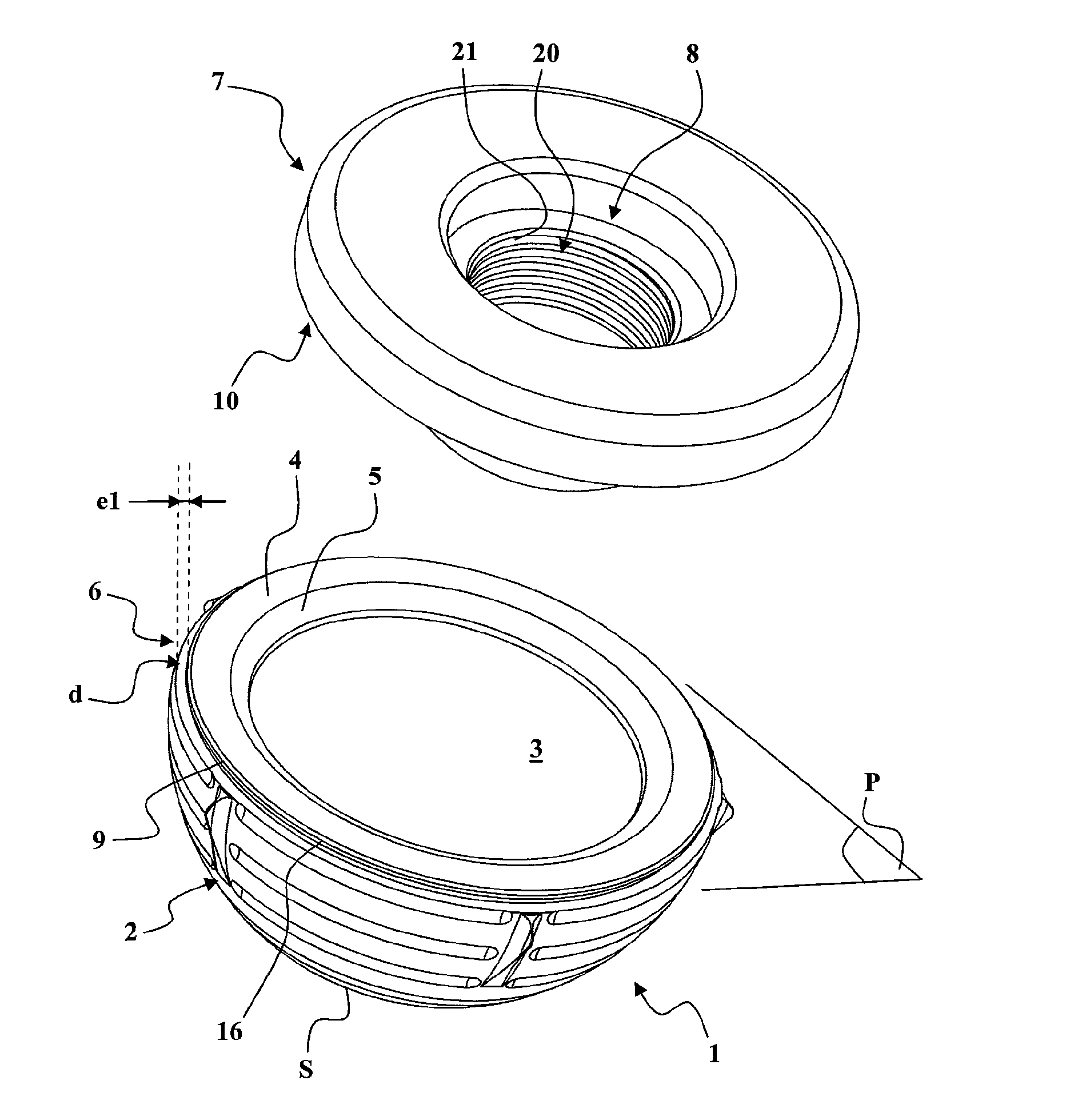
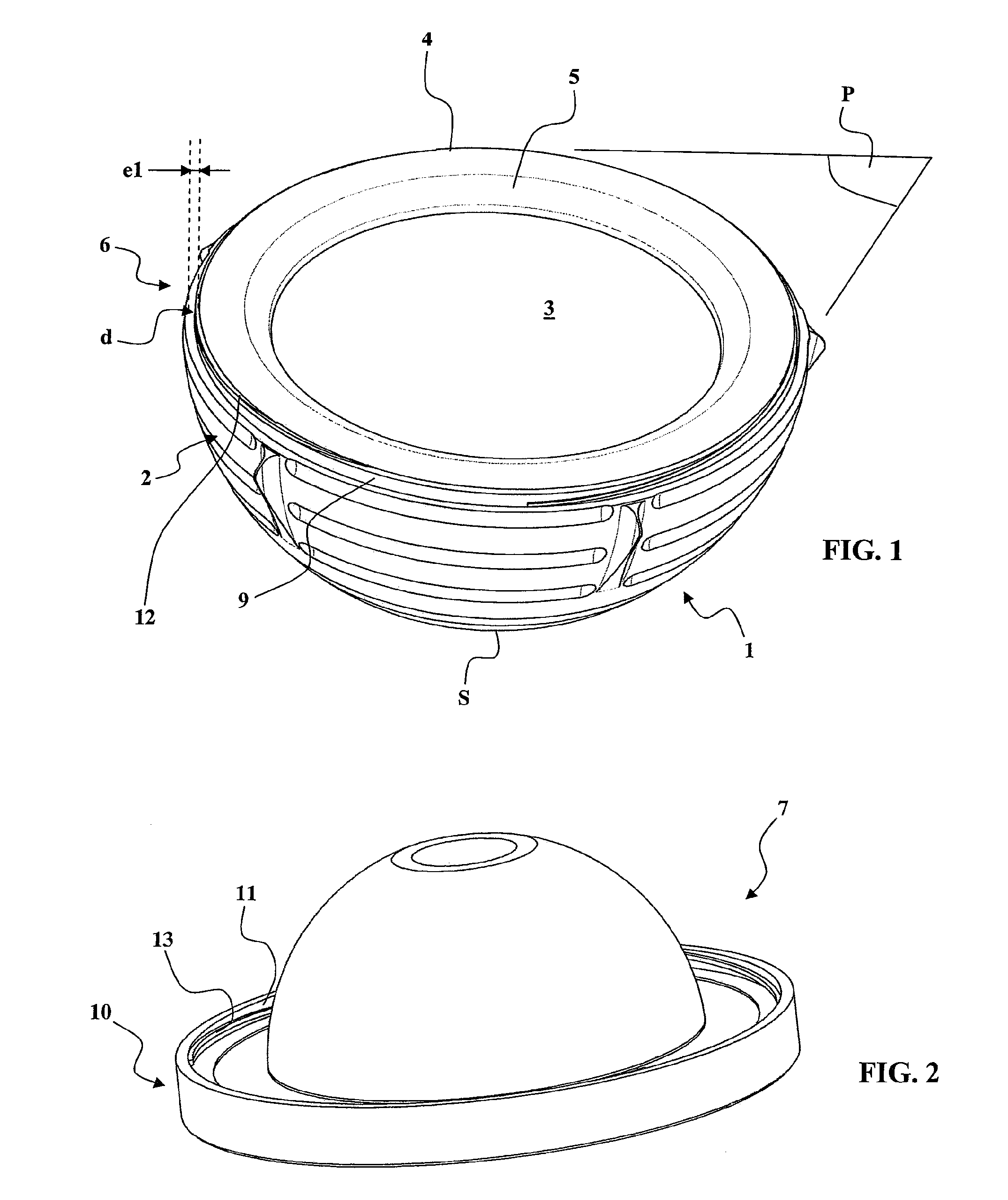
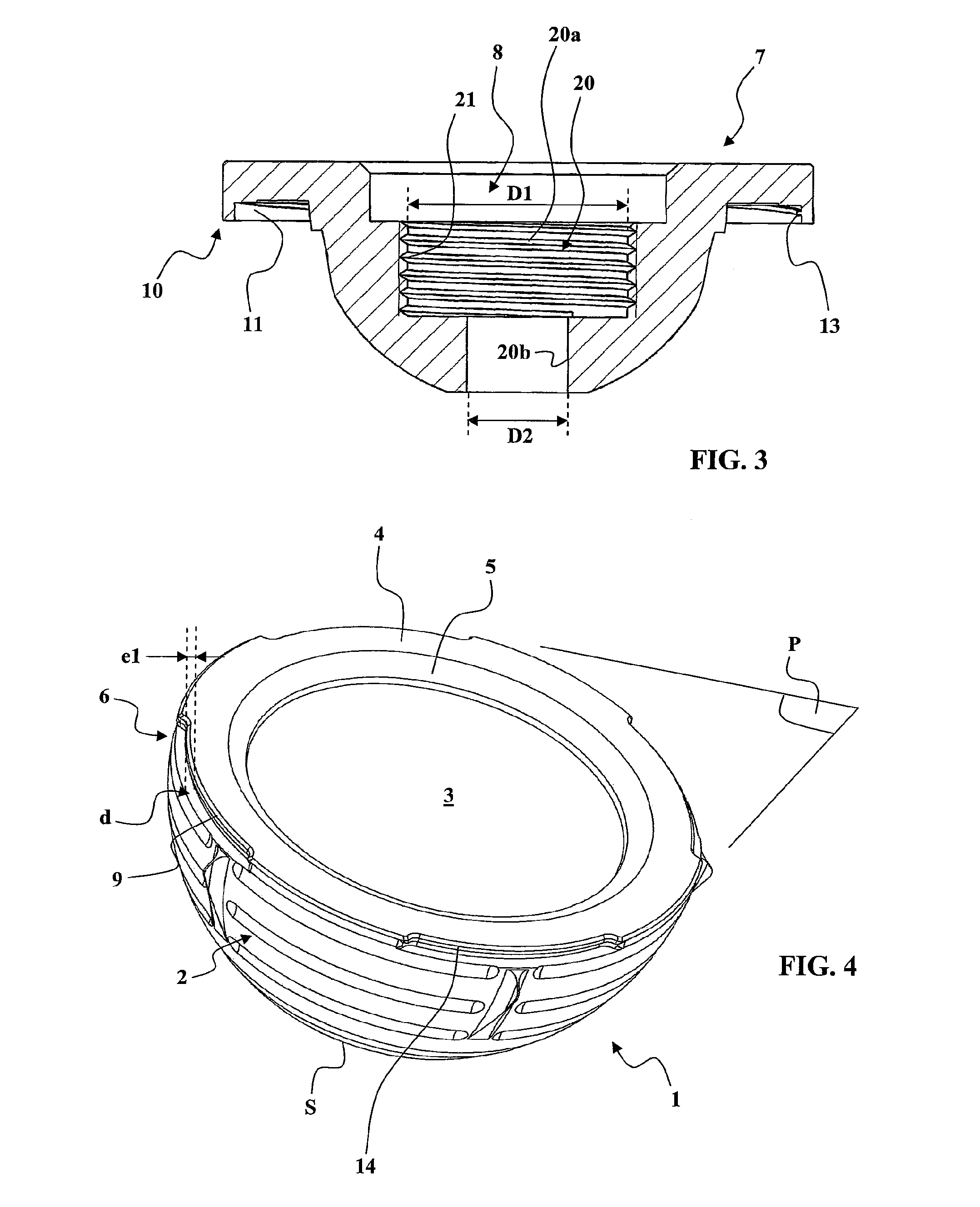
[0076]Each one of FIGS. 1, 4, 5 and 8 shows a ceramic cup 1 of a prosthetic hip acetabulum. This ceramic cup 1 comprises:[0077]a convex outer anchoring face 2, designed to be anchored in an acetabular cavity of the pelvis of a patient, and a concave inner receiving face 3 with an annular edge 4,[0078]an annular receiving structure 6 designed in such a way that an impactor can be fixed to said annular receiving structure 6 for the impaction of the cup 1 in the acetabular cavity of the pelvis of a patient.

[0079]The receiving structure 6 is external, which means that the concave inner receiving face 3 can be perfectly smooth in order to permit perfect sliding between the cup and the spherical prosthetic head.

[0080]It can be seen more particularly that:[0081]the concave inner receiving face 3 is a sphere portion having an opening face 5 contained in an opening plane P,[0082]the annular receiving structure 6 is set back from the opening plane P.

[0083]In other words, the annular receiving...


PUM

PropertyMeasurementUnit
radial thicknessaaaaaaaaaa
heightaaaaaaaaaa

Abstract

A method for producing a prosthetic acetabulum includes the following steps. First, one makes available a ceramic cup (1) that has a concave internal receiving face (3) and has an external annular receiving structure (6). Next, one makes available a placement and orientation insert (7) that has an annular peripheral fixing structure (10) designed to cooperate with the receiving face (9) of the external annular receiving structure (6) by engaging around the external annular receiving structure (6). Next, one heats the placement and orientation insert (7) in order to increase the dimensions of the insert. Next, one engages the annular peripheral fixing structure (10) around the receiving face (9) of the external annular receiving structure (6). Finally, one returns the placement and orientation insert (7) to ambient temperature in order to reduce the dimensions of the insert, in such a way as to obtain a radial clamping of the annular peripheral fixing structure (10) on the external annular receiving structure (6).

Description

TECHNICAL FIELD OF THE INVENTION[0001]The present invention relates to a method for producing a prosthetic acetabulum intended to replace the natural acetabulum of the hip.[0002]A total hip prosthesis comprises two parts constituting a ball-and-socket joint, namely a female part intended to replace the natural acetabulum of the hip, and a male part intended to replace the head of the femur. The male part of the joint generally has a shaft which is intended to engage in the medullary canal of the femur and of which the proximal end is connected by a neck to a spherical prosthetic head intended to engage in the female part. The female part of the joint, which has to replace the natural acetabulum of the hip, usually comprises a cup with a convex outer anchoring face, which is accommodated in a prepared acetabular cavity in the pelvic bone. This cup has a concave receiving face intended to directly or indirectly receive the spherical prosthetic head.[0003]When fitting the cup in the ac...

Claims


Application Information

Patent Timeline
Patent Type & Authority Patents(United States)
IPC IPC(8): A61B17/58A61F2/00A61F2/32B23P11/02A61F2/34A61F2/46A61F2/30
CPCA61F2/32A61F2/34A61F2/4609A61F2/4607A61F2002/30077A61F2002/30487A61F2002/3446A61F2002/4629A61F2310/00179Y10T29/49826
Inventor GRADEL
Owner INVENTORIO
Learn More