Dissimilar metal joining method for magnesium alloy and steel

a dissimilar metal and magnesium alloy technology, applied in the direction of resistance welding apparatus, arc welding apparatus, non-electric welding apparatus, etc., can solve the problems of difficult air joining, metallurgically very difficult to directly join materials having such characteristics to each other, etc., and achieve the effect of easy removal

Active Publication Date: 2015-11-03
NISSAN MOTOR CO LTD
View PDF50 Cites 15 Cited by
  • Summary
  • Abstract
  • Description
  • Claims
  • Application Information

AI Technical Summary

Benefits of technology

[0011]According to the present invention, the third material containing zinc and aluminum for giving rise to ternary eutectic melting with magnesium is present between magnesium alloy material and steel, thereby causing Zn—Al—Mg ternary eutectic melting when joining is made. Accordingly, if oxide film for hampering joining is formed at the joining surface, the oxide film can be easily removed from the joining interface at an extremely low temperature.
[0012]Additionally, a layer containing intermetallic compound formed between one or both of Mg and Fe which are respectively main component metals of the joined materials and Al contained in the third materials is present between the joined materials, so that mutual diffusion is made possible between the joined materials which are difficult to be metallurgically directly jointed to each other, thereby attaining a firm joining.

Problems solved by technology

When dissimilar metals are joined to each other, joining in air is difficult in case that an oxide film is present at the surface of magnesium alloy material while oxide film at the surface of steel grows at the step of heating during joining, as in the combination of magnesium alloy material and steel.
Additionally, magnesium and steel exhibit a two-phase separation type while a solubility limit to each other is very small as seen from a Fe—Mg binary phase diagram, and therefore it is metallurgically very difficult to directly join materials having such characteristics, to each other.

Method used


Image

  • Dissimilar metal joining method for magnesium alloy and steel
  • Dissimilar metal joining method for magnesium alloy and steel
  • Dissimilar metal joining method for magnesium alloy and steel

Examples


examples

[0045]Hereinafter, the present invention will be discussed in detail with reference to Examples.

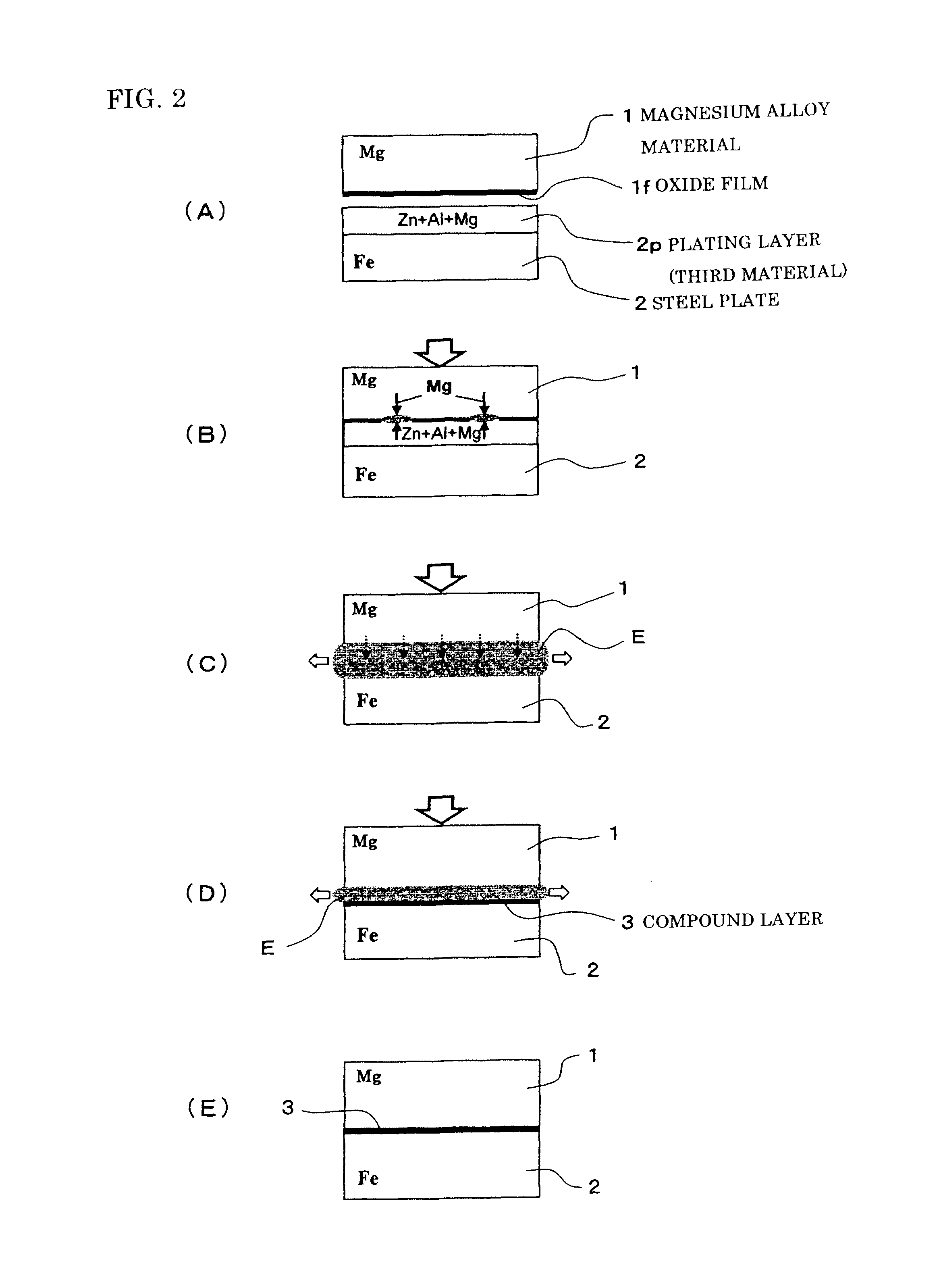
[0046]When joining of dissimilar metals which are magnesium-based material and steel was made, a steel plate plated with 11% Al-3% Mg—Zn alloy serving as a third material was used as a steel material. As a magnesium alloy material, AZ31 alloy (3% Al-1% Zn) containing aluminum was prepared. These steel material and magnesium alloy material were joined under a variety of conditions, on which researches were made on obtained relationships between interface structures and strengths, and comparisons were made to cases of using galvanized steel plates. Here, the magnesium alloy material and the steel plate used had respectively a thickness of 1.0 mm and a thickness of 0.55 mm.

[0047]FIG. 4 is a schematic illustration of a resistance spot welding apparatus used in the Examples. A joining apparatus 10 shown in the figure is proved with a pair of electrodes 11 and can accomplish joining by using he...


PUM

PropertyMeasurementUnit
temperatureaaaaaaaaaa
melting pointaaaaaaaaaa
temperatureaaaaaaaaaa

Abstract

[Object] To provide a joining method for dissimilar metals which are magnesium alloy and steel and difficult to be metallurgically directly joined to each other while oxide film is present at a joining surface.[Solving Means] In order to join magnesium alloy material 1 and steel plate 2 to each other, a galvanized steel plate to which Zn—Al—Mg alloy plating (a third material) is applied is used as the steel plate 2. When joining is made, ternary eutectic melting of Al—Mg—Zn is caused, so that it is discharged together with oxide film 1f and impurities from the joining interface while Al—Mg intermetallic compound such as Al3Mg2 and Fe—Al intermetallic compound such as FeAl3 are formed, thereby joining the newly generated surfaces of the magnesium alloy material 1 and the steel plate 2 to each other through a compound layer 3 containing these intermetallic compounds.

Description

TECHNICAL FIELD[0001]This invention relates to a method for joining dissimilar metals which are magnesium alloy and steel as a combination of dissimilar metals which are metallurgically difficult to be directly joined to each other while an oxide film is present at the joining surface thereof.BACKGROUND OF INVENTION[0002]When dissimilar metals are joined to each other, joining in air is difficult in case that an oxide film is present at the surface of magnesium alloy material while oxide film at the surface of steel grows at the step of heating during joining, as in the combination of magnesium alloy material and steel.[0003]Additionally, magnesium and steel exhibit a two-phase separation type while a solubility limit to each other is very small as seen from a Fe—Mg binary phase diagram, and therefore it is metallurgically very difficult to directly join materials having such characteristics, to each other.[0004]Accordingly, hitherto in case of using such dissimilar metal materials ...

Claims


Application Information

Patent Timeline
Patent Type & Authority Patents(United States)
IPC IPC(8): B32B15/00B23K20/02B23K20/12B23K20/16B23K20/227B23K26/24B23K26/32B32B15/01C22C18/04B23K11/20B23K11/11B23K13/01
CPCB23K20/122B23K20/16B23K20/227B23K26/244B23K26/324B32B15/013C22C18/04B23K11/20B23K11/115B23K13/01B23K20/023B23K2201/34B23K2203/18Y10T428/12729B23K2101/34B23K2103/04B23K2103/15B23K2103/18
Inventor KASUKAWA, MINORUNAKAGAWA, SHIGEYUKIMIYAMOTO, KENJI
Owner NISSAN MOTOR CO LTD
Why Eureka
Try Eureka