Systems and apparatus relating to seals for turbine engines

a technology of turbine engines and seals, applied in the direction of machines/engines, climate sustainability, sustainable transportation, etc., can solve the problems of increasing the manufacturing and maintenance cost of engines, difficult to adequately seal the gaps, and widening the gap

Active Publication Date: 2015-11-03
GE INFRASTRUCTURE TECH INT LLC
View PDF24 Cites 3 Cited by
  • Summary
  • Abstract
  • Description
  • Claims
  • Application Information

AI Technical Summary

Problems solved by technology

However, axial gaps necessarily exist between the rotating blades and the surrounding stationary parts and it is through these gaps that working fluid gains access to the wheelspace.
In addition, because of the way the engine warms up and differing thermal expansion coefficients, these gaps may widen and shrink depending on the way the engine is being operated.
This variability in size makes it difficult to adequately seal these gaps.
However, purging systems increase the manufacturing and maintenance cost of the engine, and are often inaccurate in terms of maintaining a desired level of pressure in the wheelspace cavity.
In addition, purging the wheelspace comes at a price.
As one of ordinary skill in the art will appreciate, purge flows adversely affect the performance and efficiency of the turbine engine.
That is, increased levels of purge air reduce the output and efficiency of the engine.

Method used


Image

  • Systems and apparatus relating to seals for turbine engines
  • Systems and apparatus relating to seals for turbine engines
  • Systems and apparatus relating to seals for turbine engines

Examples


Embodiment Construction

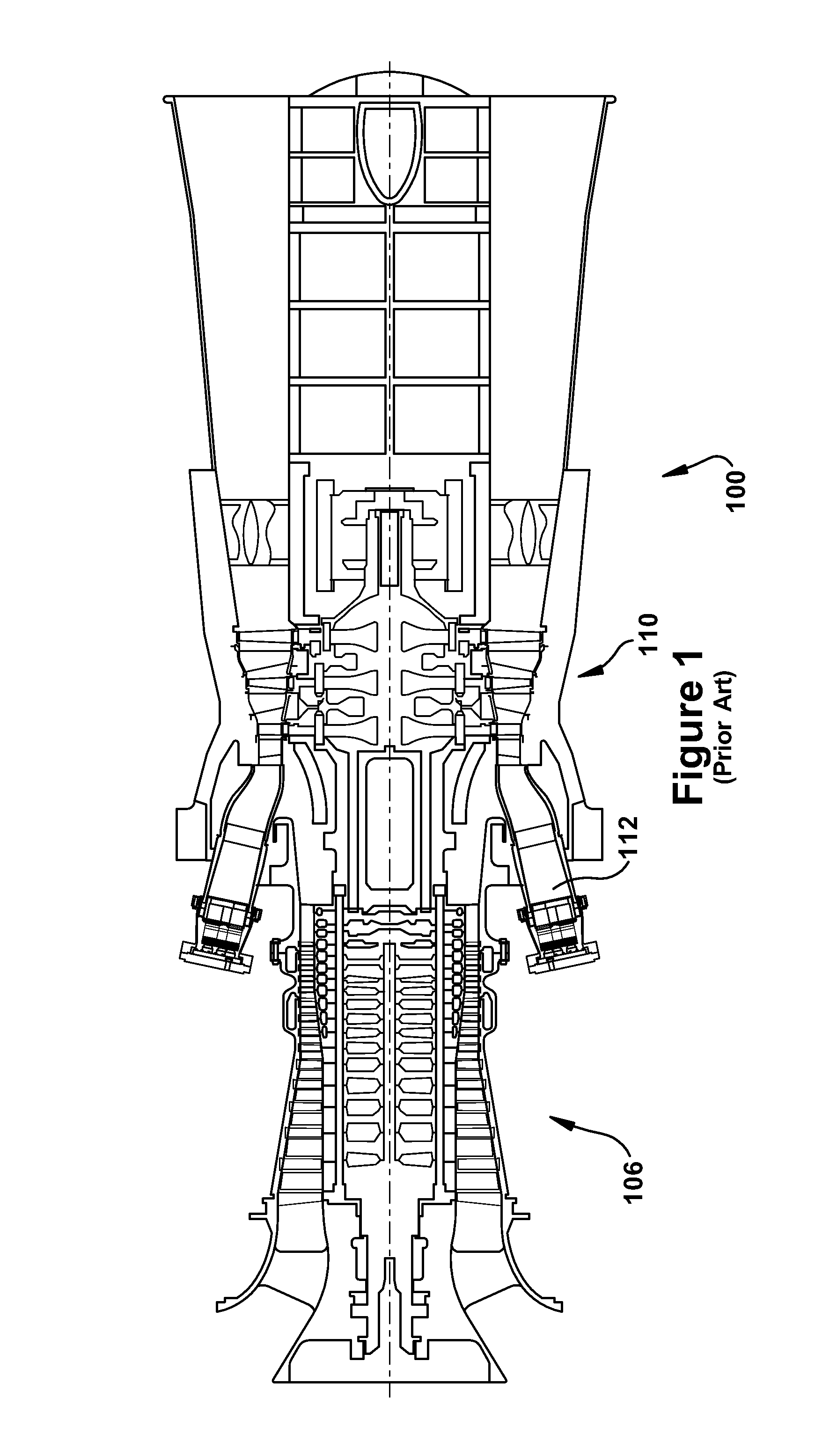
[0017]Referring now to the figures, FIG. 1 illustrates a schematic representation of a gas turbine engine 100, which will be used to describe an exemplary application of the present invention. It will be understood by those skill in the art that the present invention is not limited to this type of usage. As stated, the present invention may be used in gas turbine engines, such as the engines used in power generation and airplanes, steam turbine engines, and other type of rotary engines. In general, gas turbine engines operate by extracting energy from a pressurized flow of hot gas that is produced by the combustion of a fuel in a stream of compressed air. As illustrated in FIG. 1, gas turbine engine 100 may be configured with an axial compressor 106 that is mechanically coupled by a common shaft or rotor to a downstream turbine section or turbine 110, and a combustor 112 positioned between the compressor 106 and the turbine 110.

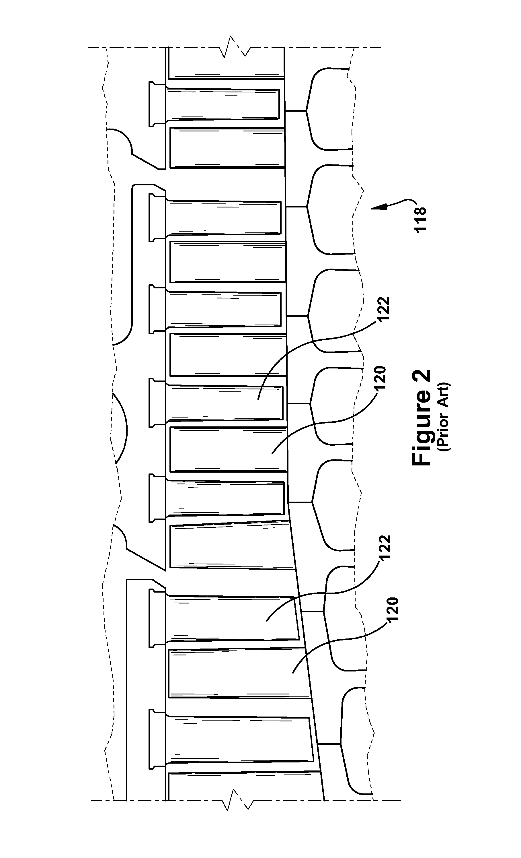
[0018]FIG. 2 illustrates a view of an exemplary multi-s...


PUM


Abstract

A seal in a turbine of a combustion turbine engine is described. The seal is formed within a trench cavity defined between a rotor blade and a stator blade. The stator blade includes a sidewall projection and the rotor blade includes an angel wing projection extending toward the stator blade. The side wall projection overhangs the angel wing projection. The seal include: a port disposed on an inboard surface of the stator projection; and deflecting structure disposed on the angel wing projection. The deflecting structure may be configured to receive the fluid expelled from the port and deflect the fluid toward an inlet of the trench cavity.

Description

BACKGROUND OF THE INVENTION[0001]The present application relates generally to systems and / or apparatus for improving the efficiency and / or operation of turbine engines, which, as used herein and unless specifically stated otherwise, is meant to include all types of turbine or rotary engines, including gas turbine engines, aircraft engines, steam turbine engines, and others. More specifically, but not by way of limitation, the present application relates to systems and apparatus pertaining to improved seals for turbine engines.[0002]In general, a gas turbine engine (which, as discussed below, may be used to illustrate an exemplary application of the current invention) includes a compressor, a combustor, and a turbine. The compressor and turbine generally include rows of blades that are axially or circumferentially stacked in stages. Each stage includes a row of circumferentially-spaced stator blades, which are fixed, and a row of rotor blades, which rotate about a central axis or sha...

Claims


Application Information

Patent Timeline
Patent Type & Authority Patents(United States)
IPC IPC(8): F01D5/08F01D11/00F01D11/04
CPCF01D5/081F01D11/001F01D11/04F05D2240/55F05D2240/81Y02T50/673Y02T50/676Y02T50/60
Inventor PORTER, CHRISTOPHER DONALDITZEL, GARY MICHAEL
Owner GE INFRASTRUCTURE TECH INT LLC
Why Eureka
Try Eureka