Two-dimensional Fresnel solar energy concentration system

a solar energy and concentration system technology, applied in solar heat systems, heat collector mounting/support, light and heating equipment, etc., can solve the problems of high capital expenditure, undesirable, and initial cost of making and installing an efficient solar energy collection system, and achieves the effects of low cost, effective and easy use, and relatively inexpensive manufacturing and installation

Active Publication Date: 2015-11-03
THE UNITED STATES OF AMERICA AS REPRESENTED BY THE SECRETARY OF THE NAVY
View PDF60 Cites 1 Cited by
  • Summary
  • Abstract
  • Description
  • Claims
  • Application Information

AI Technical Summary

Benefits of technology

The invention provides a solar energy concentrator that is easy to manufacture and use. It is lightweight and can be made with affordable materials. Additionally, the invention provides a method for erecting and maintaining solar energy collectors at a low cost with minimal labor. Overall, the invention is designed to offer a more efficient and economical solution for collecting and utilizing solar energy.

Problems solved by technology

While many of these systems are quite efficient in accomplishing the objective, i.e. collecting and storing solar energy to supplement or replace more expensive systems utilizing common sources of energy, one primary problem remains, the initial cost of making and installing an efficient solar energy collecting system.
If a solar energy collecting system is very expensive to make and install, such high capital expenditure is undesirable, since the potential user must wait too long to amortize this cost before realizing any savings in energy expense.
At the current state of the art, a principal obstacle to wide scale adoption of solar cell energy collector installations is that manufacturing and installation costs of solar cell arrays generally are substantially higher than the cost of conventional electrical energy generating installations.
Another factor limiting wide spread adoption of solar panel cells is radiant heating of the cells which reduces cell efficiency.
However, as in the case of solar cells, relatively high cost of manufacturing and relatively high installation costs have presented a principal obstacle to wide scale adoption of solar thermal energy collectors.
While the use of solar concentrators result in economic savings by increasing the effective collection area of a solar cell or thermal converter, the prior art solar concentrators themselves are costly to manufacture, and also may add appreciably to the weight of the solar energy collector system.

Method used


Image

  • Two-dimensional Fresnel solar energy concentration system
  • Two-dimensional Fresnel solar energy concentration system
  • Two-dimensional Fresnel solar energy concentration system

Examples


Embodiment Construction

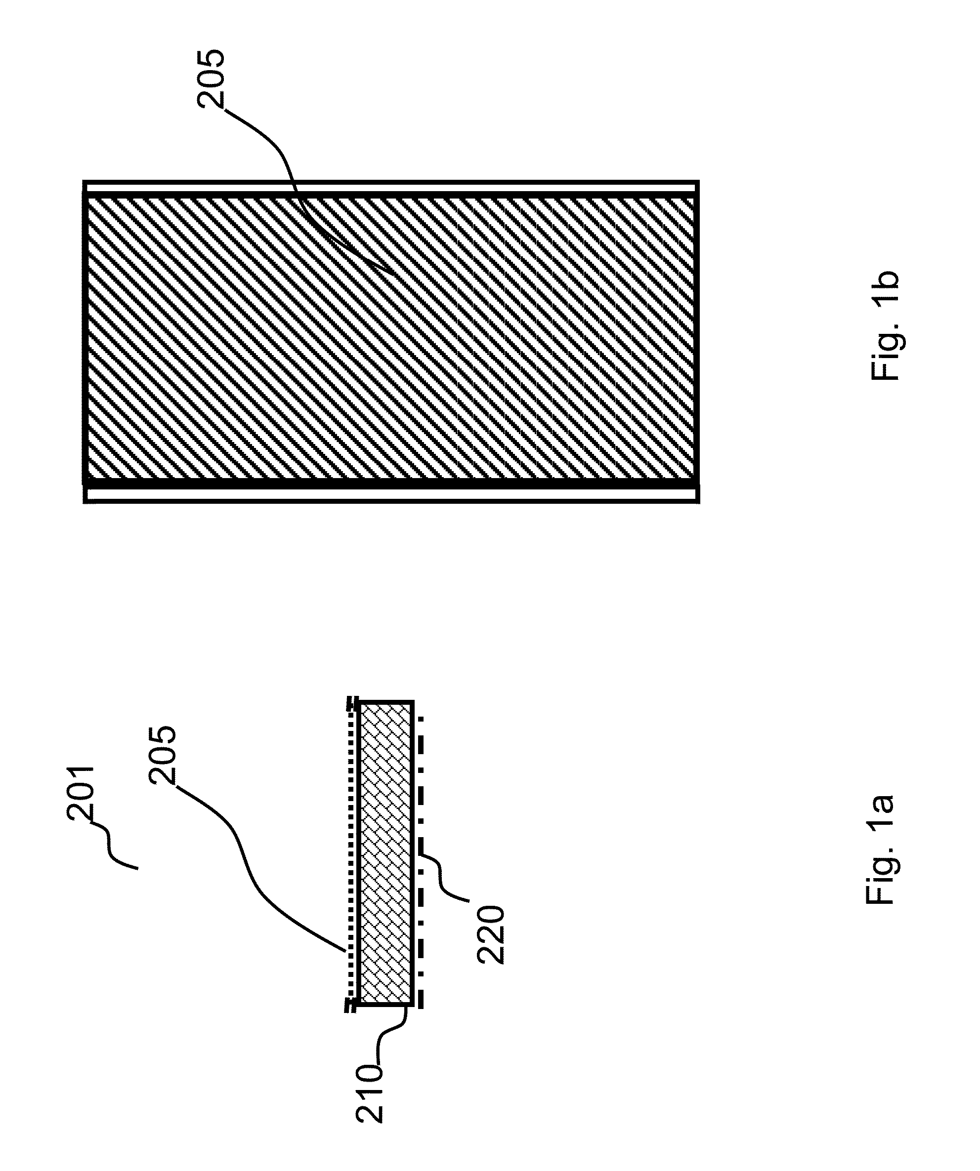
[0038]FIG. 1a is an end view of an embodiment of the instant invention showing a reflector 201. FIG. 1b is a top view of reflector 201 of FIG. 1a. The length of the collector can be relatively short as illustrated or very much longer depending on particular application needs. Typical size scales for length can be on the order of 10 meters for roof-top applications to hundreds of meters for utility-scale applications. Typical widths can be less than a meter for roof-top applications to well above a meter for utility-scale applications.

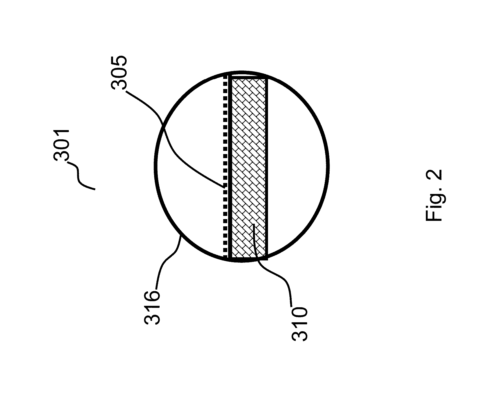
[0039]Reflector 201 comprises a reflecting film 205 with a nearly flat parabolic shape. The parabolic shape is a specific example of an approximately constant cross-section shape. The parabolic shape is also a specific example of a surface with substantial curvature in only one dimension. Reflecting film 205 is held in place and in shape by a vacuum formed support structure 210 which is an example of a vacuum formed support means for the reflecting film...


PUM


Abstract

The present invention provides a solar energy concentrating reflection system comprising multiple arrays of solar reflectors arranged adjacent to one another on a generally planar support structure where each of the reflector arrays configured into a first Fresnel array in a first dimension. Each of the first Fresnel array of reflectors are in turn arrayed and supported in a support frame in a configuration of second Fresnel arrays in a second dimension such that solar energy from the sun is reflected and concentrated to a predetermined focal line. A solar receiver is disposed in the focal line of the configured solar reflectors such that the first and second Fresnel arrays uniformly reflect and concentrate solar energy from the sun onto the solar receiver within the first and second dimensions with a uniform solar intensity profile.

Description

FEDERALLY-SPONSORED RESEARCH AND DEVELOPMENT[0001]This invention (Navy Case NC 101,522) is assigned to the United States Government and is available for licensing for commercial purposes. Licensing and technical inquiries may be directed to the Office of Research and Technical Applications, Space and Naval Warfare Systems Center, Pacific, Code 72120, San Diego, Calif., 92152; voice: (619) 553-5118; email: sscpac_t2@navy.mil.CROSS-REFERENCE TO RELATED APPLICATIONS[0002]This application is related to applications Ser. No. 13 / 017,154, filed Jan. 31, 2011, entitled “LIGHTWEIGHT SOLAR COLLECTOR ASSEMBLY AND ARRAY” (NC 100,709), Ser. No. 13 / 028,414, filed Feb. 16, 2011, entitled “TRACKING SYSTEM FOR LIGHTWEIGHT SOLAR COLLECTOR ASSEMBLY AND ARRAY” (NC 100,711), Ser. No. 13 / 110,026, filed May 18, 2011, entitled “DUAL CHAMBER SOLAR REFLECTOR SYSTEM” (NC 100,842), and Ser. No. 13 / 338,432, filed Dec. 28, 2011, entitled “VACUUM FORMED REFLECTOR FOR SOLAR ENERGY (NC 101,086), all of which are as...

Claims


Application Information

Patent Timeline
IPC IPC(8): F24J2/36F24J2/08F24J2/54F24J2/12F24S23/30F24S23/71
CPCF24J2/12F24J2/085F24J2/54F24J2002/5458F24S23/70F24S23/745F24S23/77F24S23/82F24S25/11F24S25/13F24S30/425F24S30/455F24S2023/872F24S2030/133Y02E10/47F24S23/31F24S30/40
Inventor OLSEN, RANDALL B.
Owner THE UNITED STATES OF AMERICA AS REPRESENTED BY THE SECRETARY OF THE NAVY
Why Eureka
Try Eureka