Supercharge Your Innovation With Domain-Expert AI Agents!

Circuit module

a circuit module and module technology, applied in the field of circuit modules, can solve the problems of reducing the efficiency of the circuit module b>500/b>, reducing the design flexibility, and not conducting close examinations concerning this issue, so as to reduce the efficiency of the circuit module 500, increase efficiency, and reduce the consumption of current.

Active Publication Date: 2015-11-03
MURATA MFG CO LTD
View PDF10 Cites 5 Cited by
  • Summary
  • Abstract
  • Description
  • Claims
  • Application Information

AI Technical Summary

Benefits of technology

This configuration reduces insertion loss, enhances power efficiency, and allows for a more compact design while maintaining high impedance matching, thus improving the overall performance and flexibility of the circuit module.

Problems solved by technology

However, the efficiency of the circuit module 500 is decreased by the insertion loss caused by the provision of the matching circuits.
However, close examinations concerning this issue have not been conducted so far.
Thus, in the above-described circuit module 500, it is not possible to dispose the non-reciprocal circuits 505 and 509 close to each other, thereby reducing the design flexibility.

Method used


Image

  • Circuit module
  • Circuit module
  • Circuit module

Examples


first embodiment

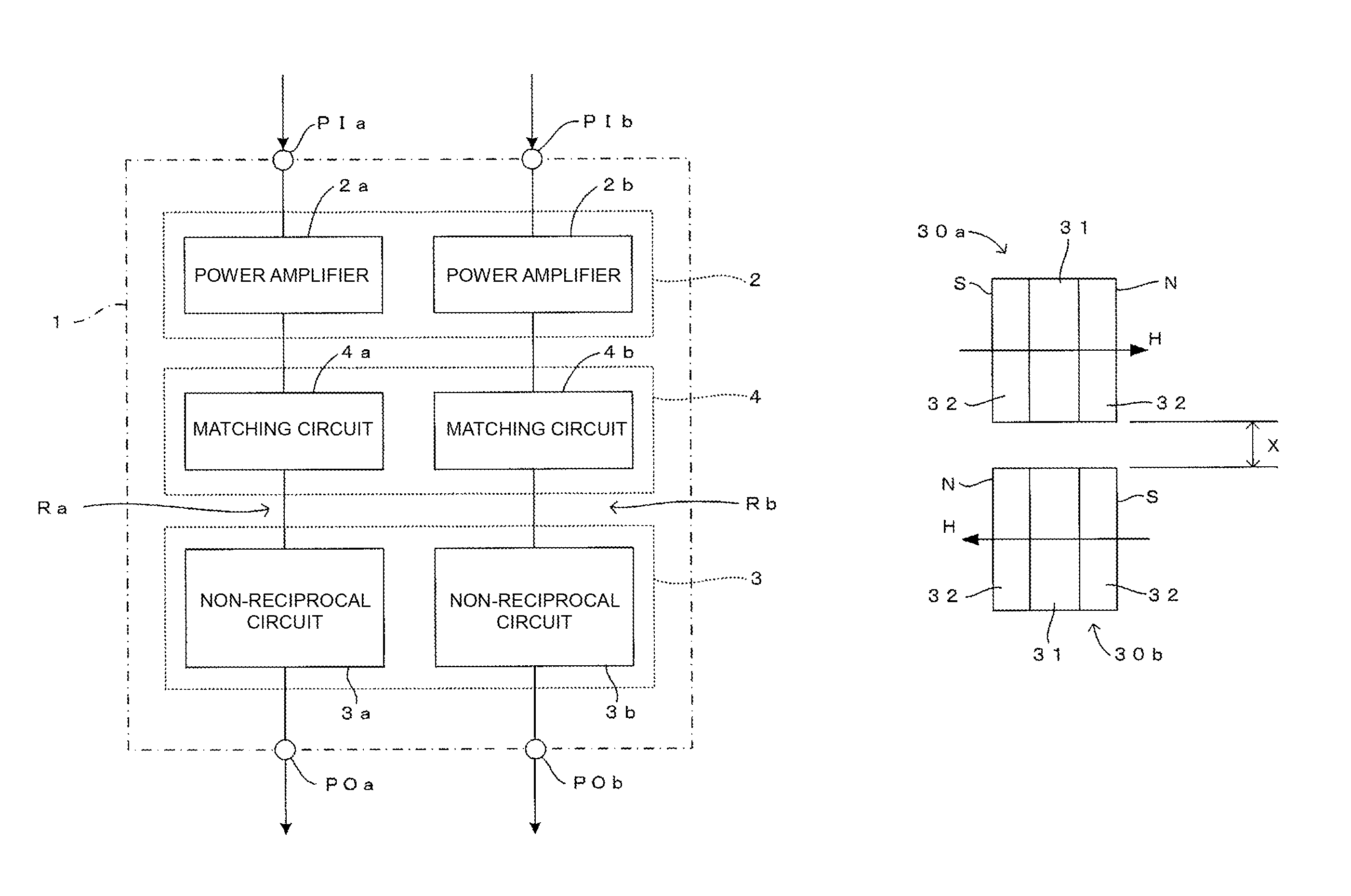
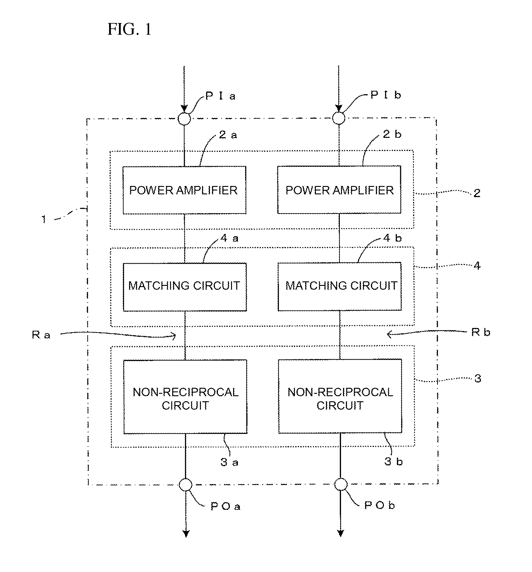
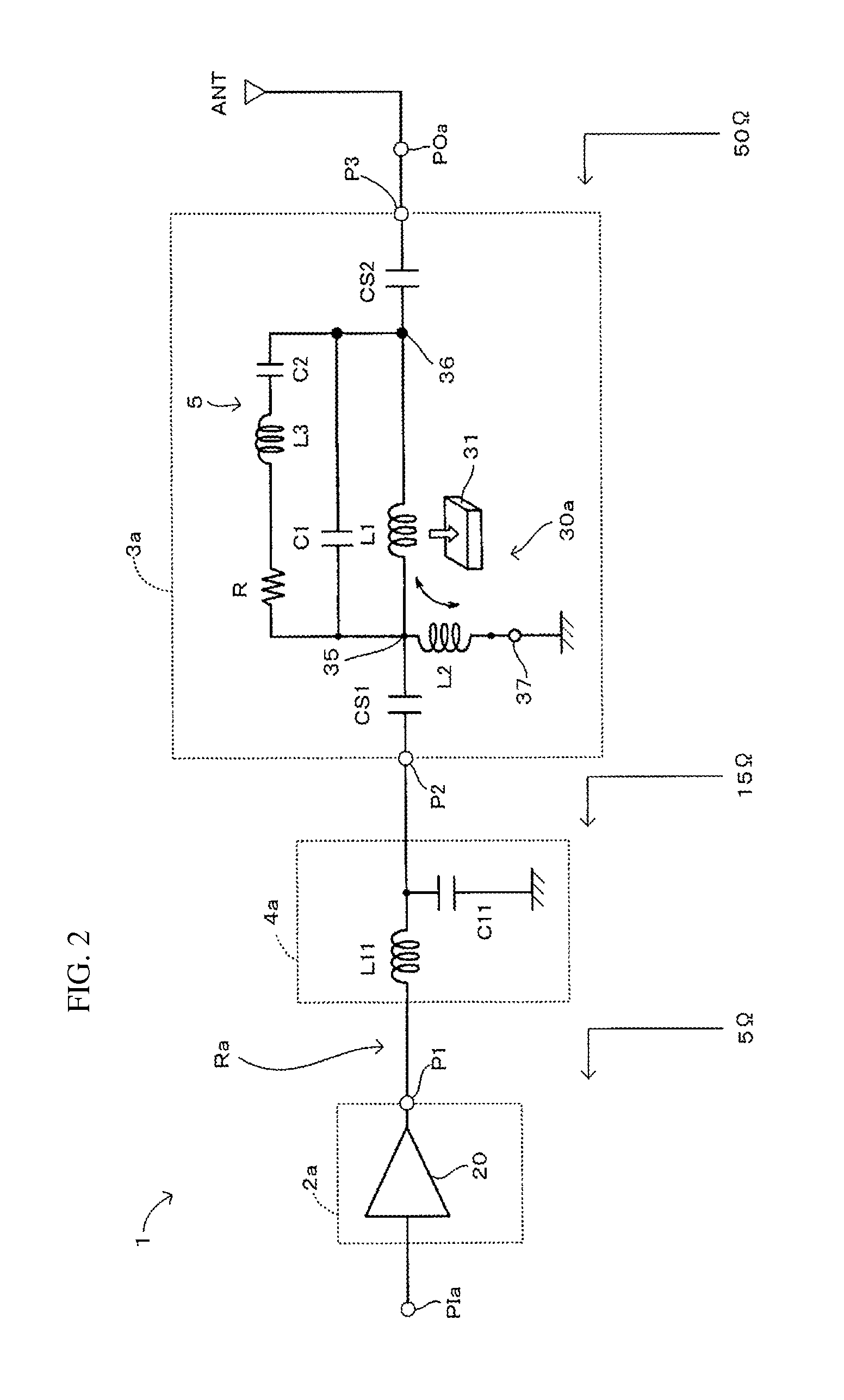
[0037]A first embodiment of a circuit module of the present invention will be described below with reference to FIGS. 1 through 5. FIG. 1 is a block diagram illustrating the first embodiment of a circuit module of the present invention. FIG. 2 is a circuit block diagram illustrating the configuration of a transmission route included in the circuit module shown in FIG. 1. FIG. 3 is an exploded perspective view illustrating ferrite and magnetic elements forming an isolator of a non-reciprocal circuit. FIG. 4 is a diagram illustrating a state in which the isolators are arranged. FIG. 5 is a graph illustrating the impedance characteristics obtained when the isolators are arranged in the state shown in FIG. 4.

[0038]A circuit module 1 shown in FIG. 1 is a power amplifier module which is formed by disposing amplifying means 2, regulating means 3, matching means 4, and so on, on a substrate made of, for example, a resin or ceramics. The circuit module 1 is used in a transmission circuit of ...

first modified example

[0060]A first modified example of the arrangement state of the isolators will be discussed below with reference to FIGS. 6 and 7. FIG. 6 is a diagram illustrating a first modified example of a state in which the isolators are arranged, and FIG. 7 is a graph illustrating the impedance characteristics obtained when the isolators are arranged in the state shown in FIG. 6.

[0061]As shown in FIG. 6, in the first modified example, the magnetic poles N and S of the permanent magnets 32 of the isolators 30a and 30b are aligned so that the directions from the magnetic pole N to the magnetic pole S will be the same. According to this arrangement state of the isolators 30a and 30b, too, as shown in FIG. 7, as the distance x between the isolators 30a and 30b decreases, the DC magnetic fields H intensify with each other more closely, and the input impedance of each of the non-reciprocal circuits 3a and 3b is reduced.

second modified example

[0062]A second modified example of the arrangement state of the isolators will be discussed below with reference to FIGS. 8 and 9. FIG. 8 is a diagram illustrating a second modified example of a state in which the isolators are arranged, and FIG. 9 is a graph illustrating the impedance characteristics obtained when the isolators are arranged in the state shown in FIG. 8.

[0063]As shown in FIG. 8, in the second modified example, the isolators 30a and 30b are disposed such that a straight line perpendicularly passing through both magnetic poles of the permanent magnets 32 of one isolator 30a intersects with a straight line perpendicularly passing through both magnetic poles of the permanent magnets 32 of the other isolator 30b. According to this arrangement state of the isolators 30a and 30b, too, as shown in FIG. 9, as the distance x between the isolators 30a and 30b decreases, the DC magnetic fields H intensify with each other more closely, and the input impedance of each of the non-...


PUM


Abstract

Isolators are disposed such that DC magnetic fields of permanent magnets intensity with each other, and thus, the input impedance of non-reciprocal circuits 3a and 3b (regulating means 3) is reduced. Accordingly, the impedance conversion ratio between the output impedance of amplifying means 2 and the input impedance of the regulating means 3 is reduced to be relatively small. Thus, by simplifying the configuration of matching means 4 disposed between the amplifying means 2 and the regulating means 3, the insertion loss of the matching means 4 can be reduced, thereby enhancing the efficiency of a circuit module 1. Additionally, it is possible to dispose the non-reciprocal circuits 3a and 3b close to each other so that the DC magnetic fields of the permanent magnets can intensity with each other, thereby increasing the design flexibility of the circuit module 1 and accordingly reducing the size of the circuit module 1.

Description

BACKGROUND OF THE INVENTION[0001]1. Field of the Invention[0002]The present invention relates to a circuit module including amplifying means for amplifying multiple types of signals.[0003]2. Description of the Related Art[0004]These days, there is an increasing demand for multiband, multimode mobile communication terminals, such as cellular phones and mobile information terminals, which support multiple communication systems of different frequency bands or different modulation methods. Therefore, on a transmission side of this type of mobile communication terminal, a circuit module that supports multiple radio frequency signals of different frequency bands is mounted, as shown in FIG. 11 (for example, see Patent Document 1). A circuit module 500 shown in FIG. 11 is a module for amplifying radio frequency signals of multiple frequency bands (Bands), and includes a transmission route R1 through which input signals RFin_BC0 (800 MHz band) and RFin_BC3 (900 MHz band) are amplified and a...

Claims


Application Information

Patent Timeline
Patent Type & Authority Patents(United States)
IPC IPC(8): H01P1/36H01P1/387H03H7/38H04B1/00
CPCH03H7/38H01P1/36H01P1/387H03H2007/386H04B1/0053
Inventor YOSHIMI, SYUNJISAITO, KENJIYANAGIHARA, SHINGOHIGASHIDE, YUKI
Owner MURATA MFG CO LTD
Features
  • R&D
  • Intellectual Property
  • Life Sciences
  • Materials
  • Tech Scout
  • Unparalleled Data Quality
  • Higher Quality Content
  • 60% Fewer Hallucinations
Learn More