Method and device for reducing angulation error during dental procedures

a technology of angulation error and dental procedures, applied in the field of angulation error reduction during dental procedures, can solve the problems of adversely affecting the accuracy of impressions, adding to the cost and time of treatment, etc., and achieve the effect of reducing angulation error

Active Publication Date: 2015-11-10
LOMA LINDA UNIVERSITY
View PDF6 Cites 4 Cited by
  • Summary
  • Abstract
  • Description
  • Claims
  • Application Information

AI Technical Summary

Benefits of technology

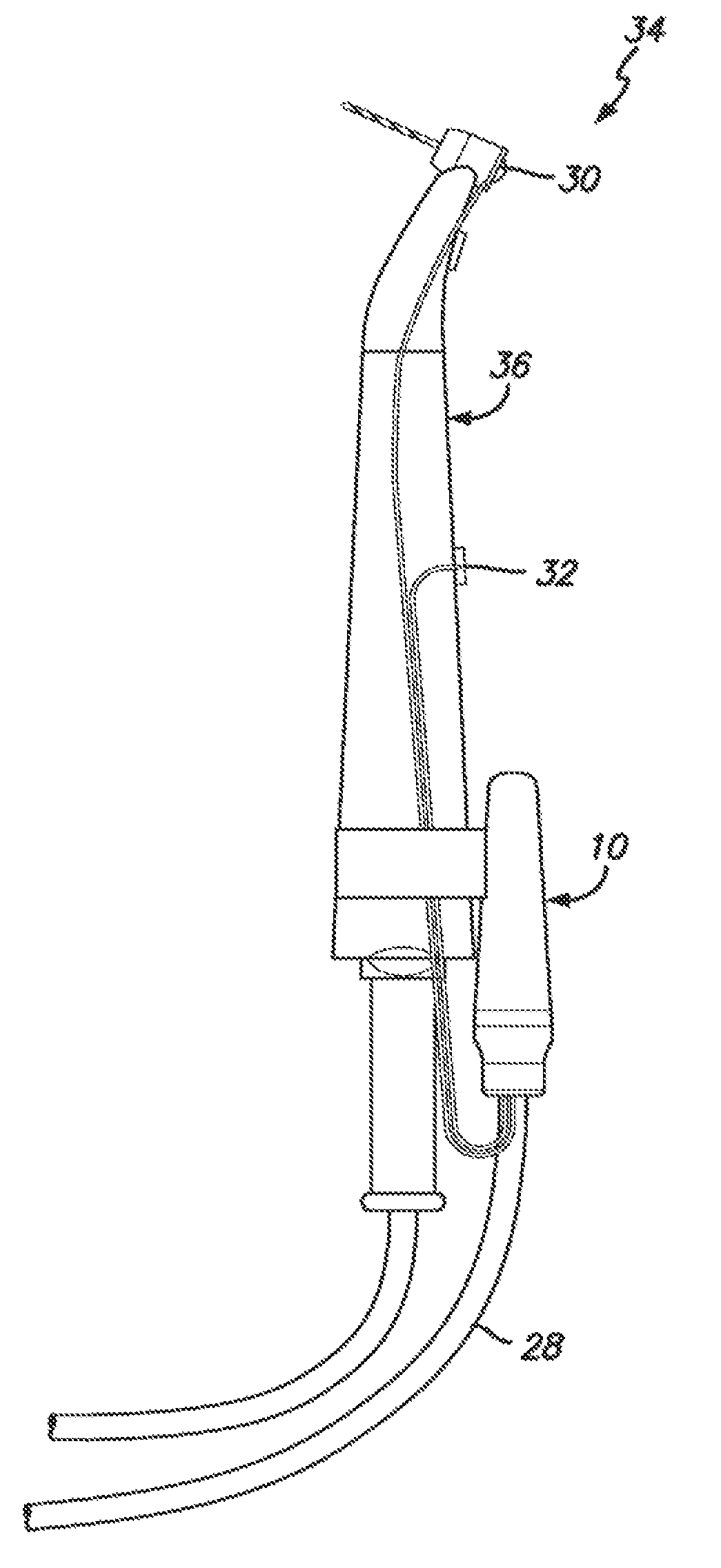
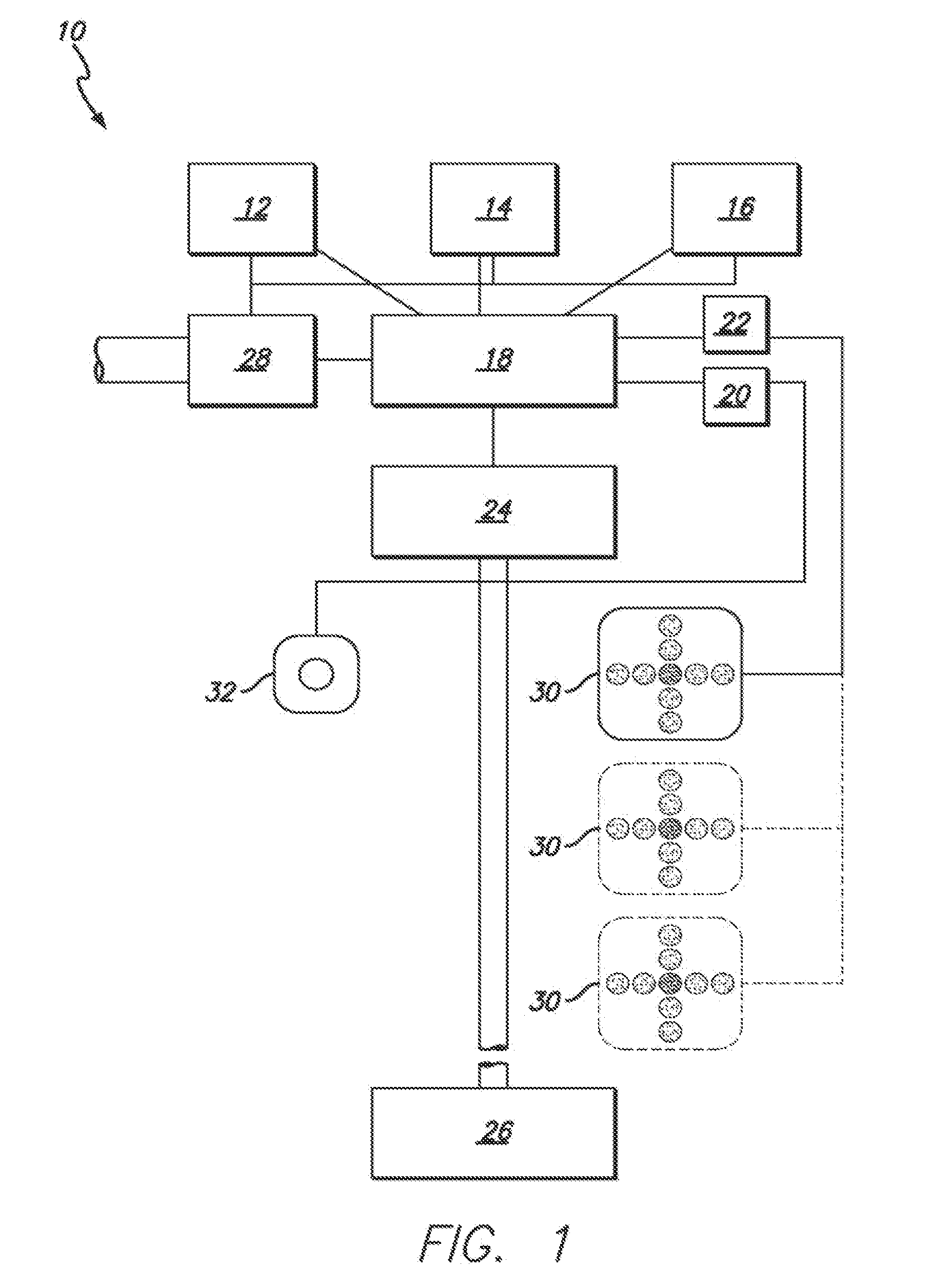
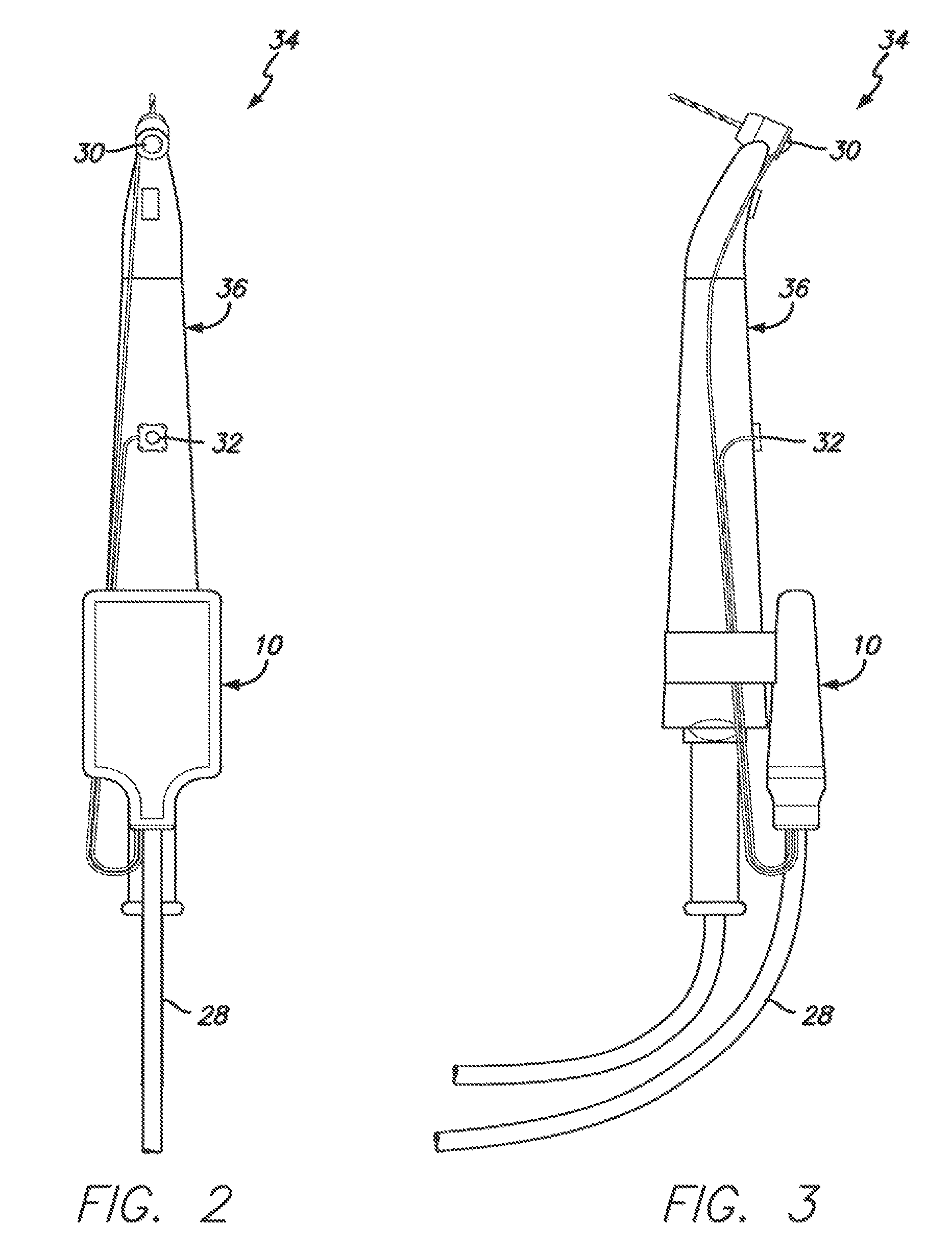
[0008]According to another embodiment of the present invention, there is provided a system for reducing angulation error during the placement of dental implants. The system comprises, a) a device with two or more sensors that monitor realtime orientation of the device in space; a programmable computer processor comprising both an input channel and an output channel connected to the two or more sensors; a computer-sensor interface for connecting to a computer for programming the device and for receiving and manipulating data from the device, the computer-sensor interface connected to the programmable computer sensor; one or more signal emitter connecter to the computer-sensor interface through the output channel for emitting one or more signal; an actuator connected to the programmable computer processor by way of the input channel; and b) a dental handpiece connected to the device. In one embodiment, the device is integrally attached to the dental handpiece. In another embodiment, the device is reversibly attached to the dental handpiece. In a preferred embodiment, the dental handpiece is a dental drill.

Problems solved by technology

Additionally, improperly aligned implants can adversely affect the accuracy of impressions.
These techniques increase the precision of the angular placement of dental implants, but disadvantageously, require cone beam computed tomography (CBCT) scans, and substantial training and pre-implant planning, thereby adding to the cost and time for treatment.

Method used


Image

  • Method and device for reducing angulation error during dental procedures
  • Method and device for reducing angulation error during dental procedures
  • Method and device for reducing angulation error during dental procedures

Examples


example i

Reduction of Angulation Error Using a System According to the Present Invention

[0039]The device, system and method according to the present invention were tested as follows. The study was performed using twenty third-year dental students and five experienced clinicians (having placed more than 100 implants). Participants were numbered using a random numbering system. Students' Perceptual Ability Test (PAT) scores on the Dental Admissions Test were obtained from school administration. Fifty mandibles (Paradigm Dental Models, San Diego, Calif., US) were mounted in dental simulators (A-December, Newberg, Oreg., US). Seven marks were drawn on each of the mandibles: one for placement of a central reference pin, two on each side as locations for osteotomy placement, and one on each side for practice. To provide a standard reference osteotomy, the central osteotomy was drilled using a jig. Prior to using the system of the present invention, each participant watched an instructional video s...


PUM


Abstract

A method for reducing angulation error during the placement of dental implants or other dental procedures. Two or more sensors are used to monitor realtime orientation of a dental handpiece. One or more signal emitters are used in order to notify the user that a first orientation of the dental handpiece has been identified and recorded. One or more signal emitters are used to notify the user that the dental handpiece has been repositioned into a second orientation having a predetermined spatial relationship to the first orientation.

Description

CROSS-REFERENCE TO RELATED APPLICATION[0001]The present application claims the benefit of U.S. Provisional Patent Application No. 61 / 610,259, titled “Method and Device for Placing Dental Implants,” filed Mar. 13, 2012, the contents of which are incorporated in this disclosure by reference in their entirety.BACKGROUND[0002]The placement of dental implants requires precise angulation for the best aesthetic result and longevity of the restorations that are fixed to the implants. Further, precise angulation is particularly important for proper implant functioning when occlusal forces are applied to the implant, as well as for prosthesis retention with overdentures. Additionally, improperly aligned implants can adversely affect the accuracy of impressions. Where two or more than two dental implants are implanted to support a restoration, precise angulation of the dental implants relative to each other is also required for the best function and longevity, and the least maintenance of the ...

Claims


Application Information

Patent Timeline
Patent Type & Authority Patents(United States)
IPC IPC(8): A61C1/08A61C13/271A61B19/00A61C8/00A61C5/08
CPCA61C8/009A61B19/5244A61C1/084A61C5/08A61C13/26A61B2019/5248A61B2034/2048A61B34/20A61C5/70A61B2562/0219A61B2562/0223A61C1/0007A61C1/082A61C1/12A61C3/02
Inventor GOODACRE, BRIAN J.
Owner LOMA LINDA UNIVERSITY
Why Eureka
Try Eureka