Terminal blocks for printed circuit boards

a technology of printed circuit boards and terminal blocks, which is applied in the direction of clamped/spring connections, electrical equipment, connections, etc., can solve the problems of rigidity, corrosion of exposed wires, and destroying the connection to lead wires, so as to facilitate automatic wire handling and facilitate connection

Active Publication Date: 2015-11-10
CONNECTING PRODS
View PDF113 Cites 6 Cited by
  • Summary
  • Abstract
  • Description
  • Claims
  • Application Information

AI Technical Summary

Benefits of technology

[0030]Up to a certain size of lead wire, the force needed to actuate the slide, which causes the insulation to be penetrated, is low enough that ordinary finger pressure can accomplish the task. But when the size of wire requires more force, than can be comfortably applied with a finger, a tool such as a handled probe pressed onto the top of the slide can more comfortably make the connection. Alternatively, a connection force may be applied automatically with powered actuation by a press machine or the like. In accordance with a further embodiment, a terminal block includes a lever which amplifies the applied force enabling manual connection.
[0031]This design enables easy automatic wire handling, which can be digitally programmed to apply wires as required for the application. It also allows terminal blocks to be prewired automatically, which is useful for high volume devices, with fixed and predetermined circuits.

Problems solved by technology

Exposed wires are subject to corrosion, especially in humid climates, coastal regions which have salt air and in environments where there is moisture.
Another drawback of terminal blocks with screw-type connectors is that in geographic regions that have wide temperature variations, such as in the northeastern United States, the temperature variations cause expansion and contraction of terminal blocks so that the screws become loose over time, destroying the connection to the lead wires.
A major disadvantage of this design is that the rigidity makes a condition where any vibration, such as from power screwdrivers, or any other maltreatment can damage the solder connections.
Even if just one connection is damaged, the whole assembly of the PCB is destroyed.
The design is also costly to manufacture.
Terminal blocks having screw type terminals to permit field connections to a PCB are subject to abusive forces directed at the relatively delicate construction of a PCB.
Field operators may be apt to use whatever tool is at their disposal, and if that tool is a 12 volt cordless impact wrench, it is going to apply its impacts to the terminal screws, with damaging results.
Many terminals only have formed and threaded internal threads, with not enough material to withstand impact type screw driving.
The small Phillips recess is not strong enough to withstand the impacts and soon wears into a smooth cone.
The impact wrench's violent seating causes the driving bit to jump out of the recess and damage the PCB.
The vibration causes the solder joints between the terminals and the PCB to fracture and lose reliable connection.
Any accidental knock which hits the terminal block will break the solder joints and the block.

Method used


Image

  • Terminal blocks for printed circuit boards
  • Terminal blocks for printed circuit boards
  • Terminal blocks for printed circuit boards

Examples


Embodiment Construction

[0051]The following is a detailed description of the invention provided to aid those skilled in the art in practicing the present invention. Those of ordinary skill in the art may make modifications and variations in the embodiments described herein without departing from the spirit or scope of the present invention. Unless otherwise defined, all technical and scientific terms used herein have the same meaning as commonly understood by one of ordinary skill in the art to which this invention belongs. The terminology used in the description of the invention herein is for describing particular embodiments only and is not intended to be limiting of the invention. All publications, patent applications, patents, figures and other references mentioned herein are expressly incorporated by reference in their entirety.

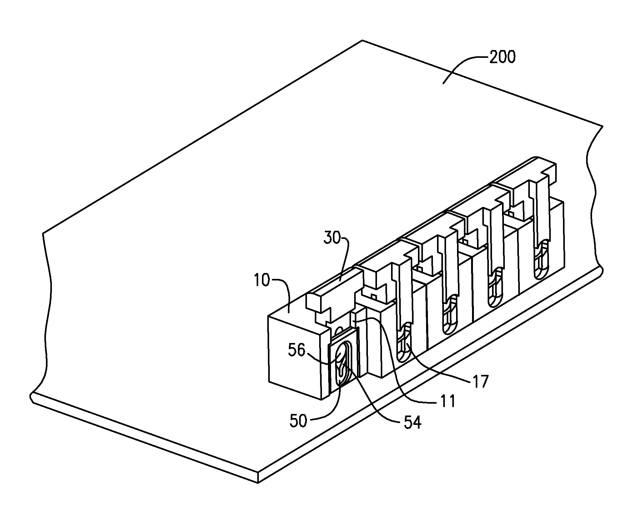
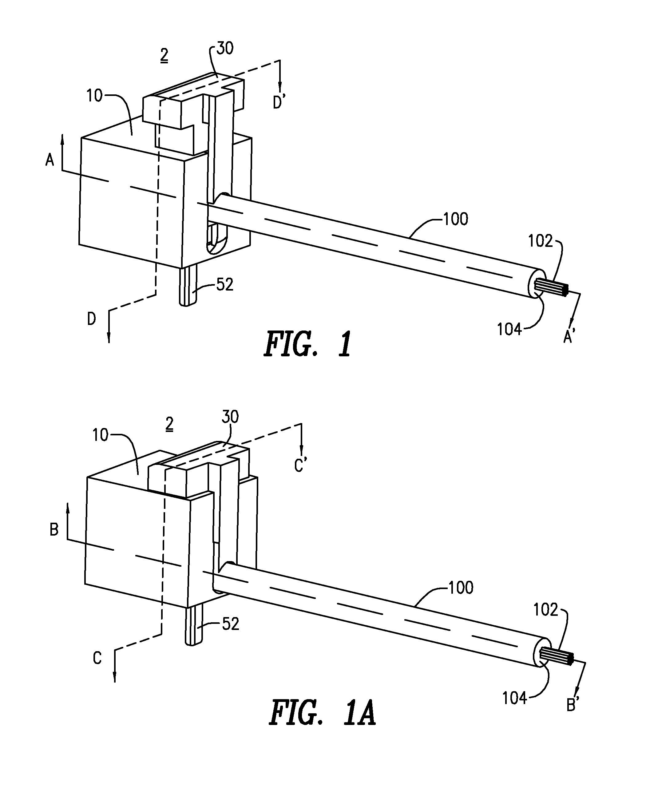
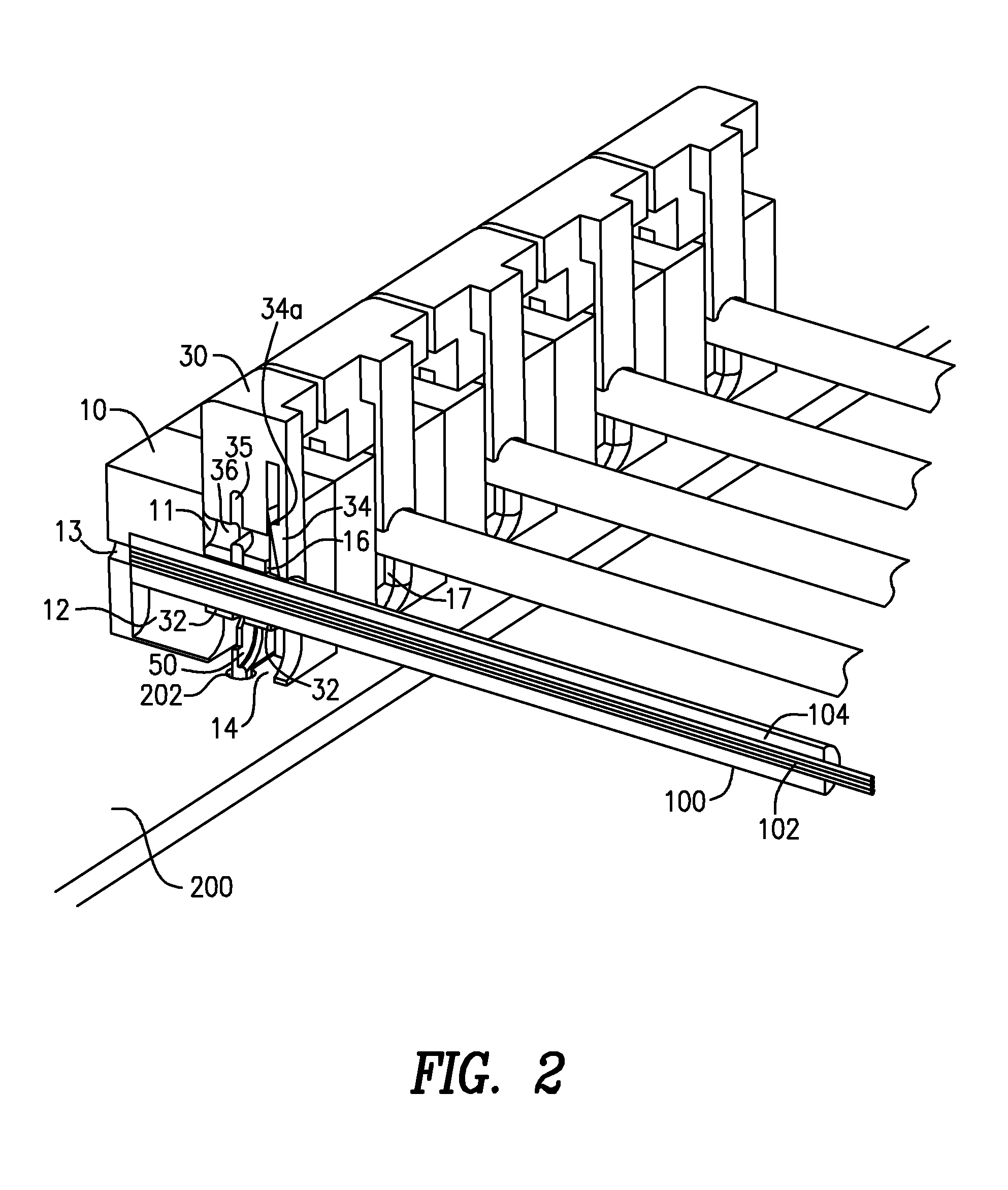
[0052]Now referring to FIG. 1, a screwless terminal block and insulation displacement connector device 2 includes a housing 10 and slide 30 slidably engaged in housing 10 opera...


PUM


Abstract

A screwless terminal block and insulation displacement connector device includes a housing and slide slidably engaged in the housing, the device operable to receive a lead wire having lead wire conductors and an insulation layer, and to further receive a conductive connector. Movement of the slide to a closed position with a lead wire inserted in the device causes the lead wire to contact sharp connector edges, which, with continued downward force, cut the insulation layer. Continued downward force, to full closure of the device, forces lead wire conductors into compressed multiple electrical contact with the connector.

Description

CROSS-REFERENCE TO RELATED APPLICATIONS[0001]This application claims the benefit of U.S. Provisional Patent Application Ser. Nos. 61 / 707,493 filed Sep. 28, 2012 and 61 / 709,479 filed Oct. 4, 2012, the entireties of which are incorporated by reference herein.FIELD OF THE INVENTION[0002]The invention relates to the field of terminal blocks for printed circuit boards.BACKGROUND OF THE INVENTION[0003]The terminal block is multi-purposed. A common purpose is to provide connecting points for a user of the parent device to make wire path connections from the power source to the controller and then on to any remote application of the power. Another purpose is to provide such possibilities of branching in the factory assembly of self-contained electrically powered and controlled units.[0004]At the printed circuit board (PCB), probes from special connectors (one for each lead wire), penetrate through holes in the PCB and are soldered in the well-known (wave soldering) manner, at the opposite s...

Claims


Application Information

Patent Timeline
Patent Type & Authority Patents(United States)
IPC IPC(8): H01R4/28
CPCH01R4/28H01R4/2433H01R12/515
Inventor FREAKES, ANTHONY
Owner CONNECTING PRODS
Why Eureka
Try Eureka